3D printing repair method of chain wheel

A 3D printing and repair method technology, applied in the direction of process efficiency improvement, additive manufacturing, coating, etc., can solve problems such as waste, scrapping, and easy wear on the chain nest, so as to improve surface strength, reduce repair costs, and avoid The effect of machining

Active Publication Date: 2016-07-06
SHANDONG ENERGY HEAVY EQUIP MFG GRP CO LTD +1
View PDF6 Cites 12 Cited by
  • Summary
  • Abstract
  • Description
  • Claims
  • Application Information

AI Technical Summary

Problems solved by technology

The sprocket of mining scraper conveyor is subjected to the alternating stress of the chain during underground use. Therefore, the chain socket is also prone to wear and tear, resulting in the sprocket not being used normally and being scrapped.
If the wear of

Method used


Image

  • 3D printing repair method of chain wheel
  • 3D printing repair method of chain wheel
  • 3D printing repair method of chain wheel

Examples


Embodiment 1

[0026] A 3D printing repair method for a sprocket, comprising the following steps:

[0027] (1) Scanning: Clean the surface defects, oxides, oil stains, etc. of the sprocket to be repaired, use a grinding wheel to polish off the surface fatigue layer until the metallic luster is exposed, and then perform a three-dimensional scan on the sprocket to obtain the surface of the sprocket Space coordinates, three-dimensional scanning technology can realize non-contact measurement, and has the advantages of fast speed and high precision;

[0028] (2) Model processing and code generation: the spatial coordinates of the sprocket surface are compared with the standard sprocket surface spatial coordinates to obtain a three-dimensional model that needs to be repaired, and then the three-dimensional model is sliced ​​to generate numerical control codes;

[0029] (3) 3D printing: first use the laser red light to align the points to determine the origin of the part to be repaired; then run th...

Embodiment 2

[0034] The same parts as those in Example 1 will not be described again. The difference is that the composition and mass percentage of the alloy powder for the primer layer are: Cr16, Mn0.4, Si0.5, Ni23 and Mo2, and the balance is Fe. The alloy powder composition and mass percentage of the cover layer are: C0.8, Cr3, Mn0.3, Si0.2, Ni8, Mo3.0, V1.0 and W5.0, and the balance is Fe.

Embodiment 3

[0036] The same part as in Example 1 will not be described again, the difference is that the alloy powder composition and mass percentage of the bottom layer are: Cr20.4, Mn0.82, Si0.71, Ni26.5 and Mo3.3 , the balance being Fe. The alloy powder composition and mass percentage of the cover layer are: C1.0, Cr4, Mn0.7, Si0.4, Ni9, Mo4.0, V1.5 and W5.5, and the balance is Fe.

[0037] Carry out microstructure test and hardness test to the repaired sprocket sample obtained in this embodiment:

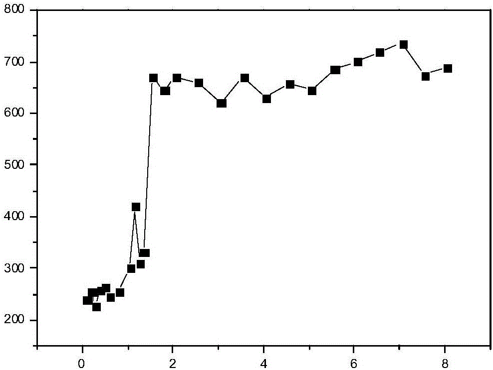
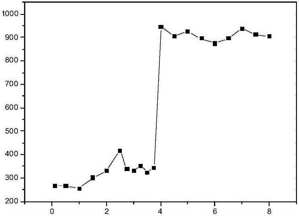
[0038] The size of the sample is 10×10×10mm. After being sanded and polished, use the HVS-1000A digital microhardness tester to test the hardness of the sample section. Floor. In order to facilitate observation, points are taken at intervals of 0.1mm in small areas, and intervals of stable hardness values ​​are 0.5mm. Hardness results such as figure 1As shown, the abscissa is the distance from the surface of the substrate (in mm), and the ordinate is the hardness test result. The averag...


PUM

PropertyMeasurementUnit
Matrix hardnessaaaaaaaaaa
Hardnessaaaaaaaaaa
Hardnessaaaaaaaaaa

Abstract

The invention discloses a 3D printing repair method of a chain wheel. The method comprises following steps: firstly, scanning, wherein the chain wheel is scanned, and space coordinates of the chain wheel surface are obtained; secondly, model processing and code generation, wherein the space coordinates of the chain wheel surface are compared with standard space coordinates of the chain wheel surface, a three-dimensional model required to be repaired is obtained, and the three-dimensional model is sliced to generate numerical control codes; thirdly, 3D printing; wherein the initial stage is printed, power of a laser device is set to range from 1200 W to 1500 W, and after 0.5 mm to 1.5 mm is printed, the power of the laser device is set to range from 600 W to 800 W; and fourthly, aftertreatment, wherein the chain wheel obtained after 3D printing is subject to sand blasting and polishing processing. According to the repair method, the wear portion can be precisely repaired, a double-coating cladding method is adopted, it is ensured that a cladding layer and a base body are completely in metallurgical bonding, and meanwhile hardness and wear resistance of the surface of the repaired position of the chain wheel can be superior to those of a new product.

Description

technical field [0001] The invention relates to the technical field of mining machinery repair, in particular to a 3D printing repair method for a sprocket. Background technique [0002] Scraper conveyors and loaders are the most commonly used and most important parts of mining machinery, and sprockets are important components of the transmission of scraper conveyors and loaders. The traction chain of the scraper conveyor and reloader is driven by the sprocket. When the sprocket rotates, the gear teeth mesh with the chain ring in turn to drive the scraper chain to move continuously, so as to transport the coal to the designated position. To withstand the maximum torque of the entire equipment, withstand pulsating loads and additional loads, the working conditions are very harsh. The sprocket of mining scraper conveyor is subjected to the alternating stress of the chain during underground use. Therefore, the chain nest is also prone to wear and tear, resulting in the sprocke...

Claims


Application Information

Patent Timeline
IPC IPC(8): B22F3/105C23C24/10B33Y10/00B33Y70/00B22F5/00C22C38/44C22C38/18C22C38/08C22C38/12C22C38/04C22C38/02
CPCC22C38/02C22C38/04C22C38/08C22C38/12C22C38/18C22C38/32C22C38/44C23C24/103B22F5/00B33Y10/00B33Y70/00B22F10/00B22F10/36B22F10/32B22F10/66B22F10/25B22F10/80Y02P10/25
Inventor 周峰杨庆东澹台凡亮杨帆何建群陶常胜杜学芸宋其伟李阳
Owner SHANDONG ENERGY HEAVY EQUIP MFG GRP CO LTD
Why Eureka
Try Eureka