Particle cutting machine

A pellet machine and pellet technology, applied in metal processing and other directions, can solve the problems of poor control of cutting length, insufficient smooth cutting plane, slow cutting speed, etc.

Inactive Publication Date: 2016-07-06
NINGBO MERRY ART GLOW TECH CO LTD
View PDF5 Cites 2 Cited by
  • Summary
  • Abstract
  • Description
  • Claims
  • Application Information

AI Technical Summary

Problems solved by technology

At present, the cutting machine used has the problems of slow cutting speed, poor control of cutting length, and insufficient smoothness of t

Method used


Image

  • Particle cutting machine
  • Particle cutting machine
  • Particle cutting machine

Examples


Embodiment

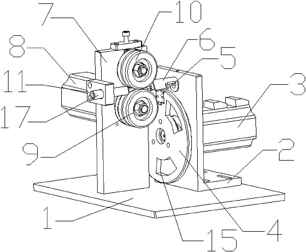
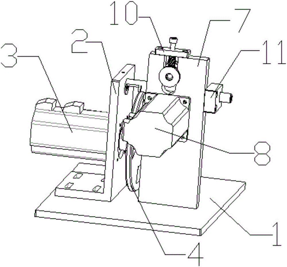
[0036] Pass the plastic rod of the fluorescent stick assembly to be cut through the guide tube 17 installed in the guide tube fixing seat 11, then pass through the gap between the driving wheel 9 and the driven wheel 10 and enter the particle cutting mold 6, and pass the adjusting screw 13 Adjust the upper and lower positions of the driven wheel 10 until the gap between the driving wheel 9 and the driven wheel 10 is adjusted to an appropriate size, and finally control the rotation speed of the servo motor 3 and the stepping motor 8 through the controller to obtain a corresponding length of fluorescent light. rod components. The invention is simple in structure, easy to use, fast in cutting speed and high in working efficiency. The cutting speed is controlled by controlling the rotating speed of the flying cutter disc through the servo motor, and the rotating speed of the driving wheel is controlled by the stepping motor, so that the cutting length can be well controlled. The c...


PUM


Abstract

The invention relates to a particle cutting machine which comprises a bottom plate, a fly-cutter disc fixing seat and a fly-cutter disc, wherein the fly-cutter disc fixing seat and a fixed plate are vertically mounted on the upper end face of the bottom plate; the fixed plate is arranged vertical to the front end face of the fly-cutter disc fixing seat; a servo motor is mounted on the back end face of the fly-cutter disc fixing seat; a rotating shaft of the servo motor is connected with the fly-cutter disc parallel to the front end face of the fly-cutter disc fixing seat; a slicing knife fixture is mounted on the edge of the fly-cutter disc; a slicing knife is mounted inside the slicing knife fixture; a particle cutting mold is mounted in the position, above the fly-cutter disc, of the front end face of the fly-cutter disc fixing seat; a stepping motor is mounted on one side of the fixed plate; a rotating shaft of the stepping motor penetrates through the fixed plate to be connected with a driving wheel; and a driven wheel capable of being adjusted up and down is mounted in the position above the driving wheel, of the fixed plate. According to the particle cutting machine, the structure is simple, the utilization is convenient, the cutting speed is high, the working efficiency is high, the cutting length can be well controlled, and the cutting surface is quite smooth.

Description

technical field [0001] The invention relates to the technical field of toy manufacturing, in particular to a pellet cutter. Background technique [0002] During the production and processing of fluorescent rods, one of the fluorescent rod components needs to be cut. At present, the cutting machine used has the problems of slow cutting speed, poor control of cutting length, and insufficient smoothness of the cutting plane. In order to solve the above problems, a special particle cutting machine for cutting fluorescent stick components is designed. Contents of the invention [0003] The technical problem to be solved by the present invention is to provide a granulator with simple structure, convenient use, fast cutting speed, high working efficiency, good control of cutting length and smooth cutting plane. [0004] The technical solution adopted by the present invention to solve the technical problem is to provide a granulator, including a base plate, a flying cutter disc f...

Claims


Application Information

Patent Timeline
IPC IPC(8): B26D1/25B26D7/06B26D7/26B26D5/08
CPCB26D1/25B26D5/086B26D7/06B26D7/2614
Inventor 陆明朗曾见忠杜军杰
Owner NINGBO MERRY ART GLOW TECH CO LTD
Why Eureka
Try Eureka