Airplane hydraulic system layout based on power-by-wire energy storage device

An energy storage device, aircraft hydraulic technology, applied in the field of hydraulic system, can solve the problems of heavy parts and increasing the weight of the aircraft

Active Publication Date: 2016-07-06
BEIHANG UNIV
View PDF4 Cites 7 Cited by
  • Summary
  • Abstract
  • Description
  • Claims
  • Application Information

AI Technical Summary

Problems solved by technology

[0013] EDP ​​and pipelines need to withstand high pressure, resulting in thicker parts, thus increasing the weight of the aircraft

Method used


Image

  • Airplane hydraulic system layout based on power-by-wire energy storage device
  • Airplane hydraulic system layout based on power-by-wire energy storage device

Examples


Embodiment Construction

[0025] Embodiments of the present application are described below with reference to the drawings. Elements and features described in one drawing or one embodiment of the present application may be combined with elements and features shown in one or more other drawings or embodiments. It should be noted that representation and description of components and processes that are not relevant to the present application and known to those of ordinary skill in the art are omitted from the drawings and descriptions for the purpose of clarity.

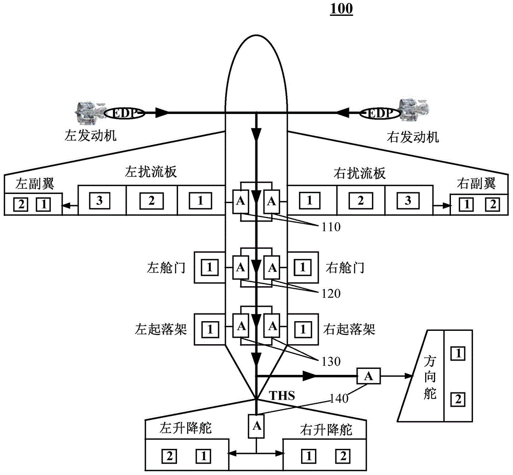
[0026] see figure 1 Shown is a structural diagram 100 of an embodiment of the layout of an aircraft hydraulic system based on a power-by-wire energy storage device of the present application.

[0027] In this embodiment, the layout of the aircraft hydraulic system based on the power-by-wire energy storage device includes a spoiler aileron accumulator 110 for driving the spoiler steering gear and the aileron steering gear;

[0028] The door acc...


PUM


Abstract

The invention relates to an airplane hydraulic system layout based on a power-by-wire energy storage device. The layout comprises spoiler flap accumulators used for driving spoiler steering engines and flap steering engines, cabin door accumulators used for driving cabin door actuators, and empennage accumulators used for driving rudder steering engines and elevating rudder steering engines, wherein the spoiler flap accumulators, the cabin door accumulators and the empennage accumulators are all connected with a fly-by-wire operation system of an airplane and used for storing energy or acting based on output commands of the fly-by-wire operation system. By the adoption of the airplane hydraulic system layout based on the power-by-wire energy storage device, the installed power of the airplane can be reduced.

Description

technical field [0001] The present application relates to the field of hydraulic systems, in particular to an aircraft hydraulic system layout based on a power-by-wire energy storage device. Background technique [0002] The aircraft hydraulic system is one of the main onboard systems of the aircraft. The control and actuators of the main control system and auxiliary control system of modern aircraft use hydraulic pressure as the energy source, and hydraulic actuators or hydraulic motors as the actuators. The aircraft hydraulic system refers to the complete set of devices on the aircraft that use oil as the working medium and rely on oil pressure to drive the actuator to complete specific manipulation actions. In order to ensure the reliability of the hydraulic system, especially to improve the reliability of the hydraulic power source of the flight control system, most modern aircraft are equipped with two (or more) independent hydraulic systems. They are respectively cal...

Claims


Application Information

Patent Timeline
Patent Type & Authority Applications(China)
IPC IPC(8): B64C13/40B64C13/50F15B1/02
CPCB64C13/40B64C13/50F15B1/02
Inventor 焦宗夏刘晓超尚耀星李兴鲁
Owner BEIHANG UNIV
Why Eureka
Try Eureka