
Multifunctional Hull cell system

A Hall cell, multi-functional technology, applied in the direction of plating tanks, electrodes, cells, etc., can solve the problems of difficult to simulate the production site, no stirring device installed, uniform thickness distribution of electrodeposited layer and scientific evaluation of internal stress state, etc. problem, to achieve the effect of easy implementation, simple structure and perfect function

Inactive Publication Date: 2016-07-06
HENAN POLYTECHNIC UNIV
View PDF6 Cites 1 Cited by
  • Summary
  • Abstract
  • Description
  • Claims
  • Application Information

AI Technical Summary

Problems solved by technology

Although this feature is conducive to the evaluation and analysis of electrodeposition effects under different current densities, such as hardness and morphology, it cannot scientifically evaluate the uniformity of thickness distribution and internal stress state of electrodeposited layers.
In addition, most of the existing Hall tanks do not have a temperature control system, so they cannot be tested according to the temperature required by production. In addition, most of them do not have a stirring device close to the production site, resulting in low reference value for the test results on the production site.
In short, although the current Hall cell has various functions, it still has some shortcomings, such as it is difficult to simulate the real production site, and the analysis function indicators are not comprehensive enough.

Method used


Image

  • Multifunctional Hull cell system
  • Multifunctional Hull cell system

Examples


Embodiment Construction

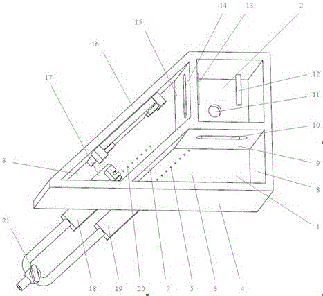
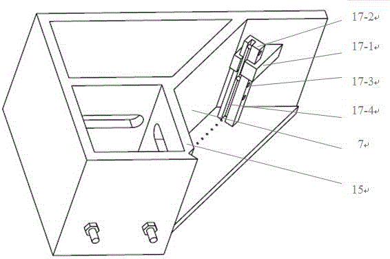
[0025] Combine below figure 1 and figure 2 The implementation of the invention is further described in detail: a multifunctional Hall cell system, which includes a Hall cell 1 , an adjustment cell 2 , and an electrodeposition cell 3 . The length of the anode wall 7 of the Hall cell is 85 mm, the length of the cathode wall is 127 mm, the length of the long side wall is 212 mm, the length of the short side wall is 120 mm, and the volume of the Hall cell is 1000 ml. The electrodeposition tank 3 is provided with a cathode clamping unit 17, and the cathode clamping unit 17 includes a clamping rod 17-2, a positioning plate 17-1 and a fixing member 17-3 provided with a straight groove 17-4; the straight groove 17-4 The axis is parallel to the cathode wall 7; the adjustment tank 2, the Hall tank 1 and the electrodeposition tank 3 share the bottom plate 6; the Hall tank 1 and the electrodeposition tank 3 share the cathode wall 7; the Hall tank 1 and the adjustment tank 2 share the sh...


PUM


Abstract

The invention discloses a multifunctional Hull cell system. The system comprises a regulating cell, a Hull cell and an electrodeposition cell, wherein a cathode clamping unit is arranged in the electrodeposition cell and comprises a clamping bar, a locating plate and fixing parts; the clamping bar is provided with a straight channel; the axis of the straight channel is parallel to a cathode wall; the regulating cell, the Hull cell and the electrodeposition cell share a bottom plate; the Hull cell and the electrodeposition cell share the cathode wall; the Hull cell and the regulating cell share a short side wall; the electrodeposition cell and the regulating cell share a side wall; a row of liquid inlets is formed in bottom plates of the Hull cell and the electrodeposition cell respectively; a liquid outlet is formed in a bottom plate of the regulating cell; overflow ports are formed in the short side wall of the Hull cell and the side wall of the electrodeposition cell. The system has the advantages that the functions of the system are further perfected; not only does the system have all the functions of existing conventional Hull cells but also the system can evaluate the distribution characters of the indexes of electrodeposition layers, such as internal stress, hardness and thickness, under the process condition of being close to production; the system has a simple structure and is low in cost.

Description

technical field [0001] The invention relates to the field of electrodeposition devices and equipment, in particular to a multifunctional Hall cell system. Background technique [0002] Hall cell, also known as Hastelloy cell or Hull cell, is a necessary device for Hall cell test. The Hall cell is an indispensable tool for electrodeposition research due to its advantages of good test effect, simple operation, and less liquid consumption. [0003] Nevertheless, existing Hall cell test setups still have limitations. The hallmark characteristics of the Hall cell are: high current density near the cathode and thick coating, low current density far away from the cathode and thin coating. Although this feature is conducive to the evaluation and analysis of electrodeposition effects under different current densities, such as hardness and morphology, it cannot scientifically evaluate the uniformity of thickness distribution and internal stress state of the electrodeposited layer. ...

Claims


Application Information

Patent Timeline
IPC IPC(8): C25D17/02C25D21/10C25D21/02C25D17/10
CPCC25D17/02C25D17/10C25D21/02C25D21/10
Inventor 刘伟陈月涛明平美李欣潮赵云龙张艳华赵晨昊杨文娟
Owner HENAN POLYTECHNIC UNIV
Learn More