Compensation type air pipe leakage prevention structure of ventilation and air conditioning system and air pipe section machining method

An air-leakage structure, air-conditioning system technology, applied in the direction of pipes/pipe joints/fittings, flange connections, pass-through components, etc., can solve the lack of innovative system air leakage core key technologies, lack of active adaptation to medium characteristics, and lack of air leakage mechanism Thorough theoretical analysis and other issues to achieve the effect of convenient splicing, light weight and simple structure

Active Publication Date: 2016-07-06
SCEGC EQUIP INSTALLATION GRP COMPANY
View PDF8 Cites 3 Cited by
  • Summary
  • Abstract
  • Description
  • Claims
  • Application Information

AI Technical Summary

Problems solved by technology

[0005] Through the preliminary theoretical discussion and the quality tracking and scientific and technological novelty search of the whole process of metal air duct processing, assembly and installation, it is found that there are still some problems in the control of air leakage in the ventilation and air conditioning system, which are mainly manifested in the following five aspects: first, Existing research is unclear about the main areas of air leakage in the system; second, the impact of quality defects in each link of metal air duct production on air leakage in the system is unclear; third, there is a lack of thorough understanding of the air leakage mechanism of key parts Theoretical analysis; fourth, there is no innovation of the core key technology to reduce the air leakage of the system, only passive actions such as plugging are adopted, and there is no active action to actively adapt to the characteristics of the medium and the actual situation; fifth, more research has been done on the detection of air leakage devices in the system , but very little research on airtight principles and putting them into practice

Method used


Image

  • Compensation type air pipe leakage prevention structure of ventilation and air conditioning system and air pipe section machining method
  • Compensation type air pipe leakage prevention structure of ventilation and air conditioning system and air pipe section machining method
  • Compensation type air pipe leakage prevention structure of ventilation and air conditioning system and air pipe section machining method

Examples


Embodiment 2

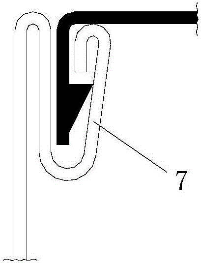
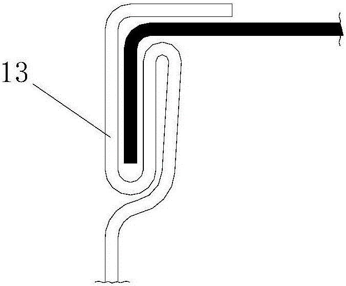
[0210] Such as Figure 5-2 with Figure 6-2 As shown, in this embodiment, the difference between the air leakage prevention structure of the compensation type metal air duct used in the ventilation and air conditioning system and that of Embodiment 1 is that: the air duct flange is an angle steel flange; the two angle steel flanges The flange sides 2 are all right-angle steels fixed on the outside of the connecting end of the air duct joint 1 or the connecting pipe fitting, and the connecting end of the air duct pipe joint 1 or the connecting pipe fitting is provided with a Flange 4 on the inside of the right-angle steel angle.

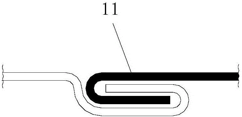
[0211] The arc-shaped sealing strip 5-1 of the Ω-shaped sealing strip 5 is located outside the folded edge 4, and the arc-shaped sealing strip 5-1 is clamped between the two flange sides 2 of the angle steel flange, The side sealing strip 5-2 of the Ω-shaped sealing strip 5 is clamped between the folded edges 4 inside the two flange sides 2; the O-s...


PUM

PropertyMeasurementUnit
thicknessaaaaaaaaaa
thicknessaaaaaaaaaa

Abstract

The invention discloses a compensation type air pipe leakage prevention structure of a ventilation and air conditioning system. The compensation type air pipe leakage prevention structure comprises a compensation type sealing structure, wherein the compensation type sealing structure comprises a compensation type sealing strip; the compensation type sealing strip is located between two flange edges of an air pipe flange; the two flange edges are fixed through a clamping structure or a connection bolt; the compensation type sealing strip is an opening type sealing strip or a closed type sealing strip; the opening type sealing strip is an omega-shaped sealing strip; and the closed type sealing strip is an O-shaped sealing strip. The compensation type air pipe leakage prevention structure is simple in form, reasonable in design, convenient to mount and good in use effect, and can be used for reducing an air leakage mount of an air pipe of the ventilation and air conditioning system effectively. Meanwhile, the invention discloses an air pipe section machining method. The air pipe section machining method comprises the following steps: step 1, cutting a metal sheet; step 2, carrying out seam machining; step 3, machining the flange edges; step 4, bending a plate of a pipe section body; and step 5, sewing a seam and compacting. The machining method has the advantages of simple steps, convenience for manufacturing and good use effect and can be used for conveniently and rapidly finishing a air pipe section machining process.

Description

technical field [0001] The invention belongs to the technical field of ventilation and air-conditioning system construction, and in particular relates to an anti-leakage structure of a compensated air duct of the ventilation and air-conditioning system and a processing method for the joints of the air duct. Background technique [0002] The ventilation and air conditioning system is composed of a ventilation system and an air conditioning system. The ventilation system is composed of supply and exhaust fans, air ducts, air duct components, mufflers, etc.; and the air conditioning system is transported and distributed by air conditioning cold and heat sources, air handlers, and air delivery pipes. And the automatic control and adjustment of the air conditioner to the indoor temperature, humidity, airflow speed and cleanliness. Today, the energy wasted by ventilation and air conditioning systems due to air leakage is undoubtedly a major component of building energy consumption...

Claims


Application Information

Patent Timeline
Patent Type & Authority Applications(China)
IPC IPC(8): F16L23/16B23P15/00B21D39/02B21D35/00
CPCB21D35/002B21D39/02B23P15/00F16L23/16
Inventor 李兴武冯璐薛新铭胡春林秦文敏史均社房海峰
Owner SCEGC EQUIP INSTALLATION GRP COMPANY
Why Eureka
Try Eureka