Smoke dust and smoke sampling device

A flue gas sampling and smoke dust technology, applied in the direction of sampling device, sampling, measuring device, etc., can solve the problems of inner pipe blockage, unfavorable detection, unreasonable arrangement of water-cooling pipes, etc., and achieve not easy deformation, good cooling effect, Facilitate follow-up detection and analysis of research results

Active Publication Date: 2016-07-06
CENT SOUTH UNIV
View PDF11 Cites 14 Cited by
  • Summary
  • Abstract
  • Description
  • Claims
  • Application Information

AI Technical Summary

Problems solved by technology

However, there is a lot of dust in the metallurgical boiler, and the sampling device is not equipped with any dust blocking parts. If it is directly used to sample the flue gas in the metallurgical boiler, not only will the dust content of the sampled flue gas be high, but it will also easily lead to The inner pipe is blocked by smoke and dust
In addition, the arrangement of the water-cooling pipes in the device is not reasonable
The water inlet pipe goes deep into the front end of the outer pipe, and the outlet pipe head is set in the middle of the rear end of the outer pipe. This arrangement will easily cause the cooling water to fail to fill the space between the outer pipe and the inner pipe, resulting in poor cooling effect.
[0005] In addition, Chinese patent 201120449605.0 discloses a high-temperature flue gas water-cooled jacket sampler, including a circulating water outer casing welded into a closed circulating water jacket, a circulating water inner pipe, a circulating water inner casing, a water inlet pipe, and a water outlet pipe. Among them, the iron slag is filled between the sampling pipe and the circulating water inner casing, and the outer wall of the samp

Method used


Image

  • Smoke dust and smoke sampling device
  • Smoke dust and smoke sampling device

Examples


Embodiment Construction

[0024] The embodiments of the present invention will be described in detail below with reference to the accompanying drawings, but the present invention can be implemented in various ways defined and covered by the claims.

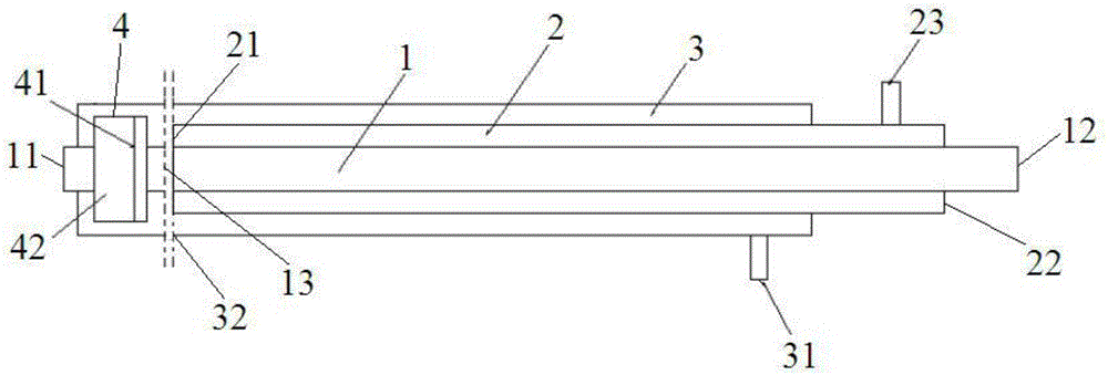
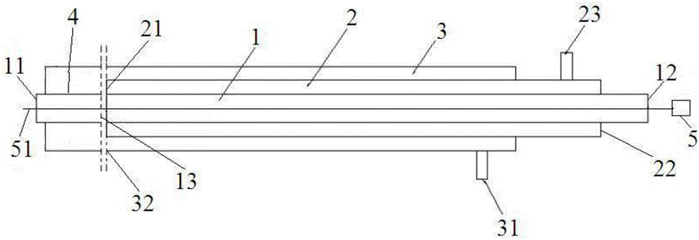
[0025] see figure 1 A dust and flue gas sampling device, comprising a sampling inner pipe 1, a cooling middle pipe 2, and a cooling outer pipe 3 respectively arranged along the horizontal direction, one end of the cooling middle pipe 2 in the length direction is closed and the other end is open, and there are 3 sets of cooling outer pipes Outside the cooling tube 2 and both ends in the length direction are closed, wherein the open end 21 of the cooling tube 2 is located in the cavity of the cooling outer tube 3, and the closed end of the cooling tube 2 passes through the wall of the cooling outer tube 3 and extends to the cooling tube. Outside the outer tube 3, the inner cooling tube 2 is covered with a sampling inner tube 1, and one end of the sampling in...


PUM


Abstract

A smoke dust and smoke sampling device comprises a sampling inner tube (1), a cooling middle tube (2) and a cooling outer tube (3).A sealed two-layer tubular sleeve type structure is formed outside the sampling inner tube by the cooling outer tube and the cooling middle tube in an enclosing mode, the sampling inner tube penetrates through the cooling middle tube, and the cooling middle tube is embedded in the cooling outer tube in a sleeved mode.According to the sampling device, the space between the outer tube and the middle tube and the space between the middle tube and the inner tube can be filled with cooling water, and therefore deformation, caused by high temperature in a metallurgical furnace, of a sampling rod cannot occur; the cooling water enters the sampling device from the portion, located below the closed end of the cooling middle tube, of the cooling outer tube and flows out of the upper portion of the closed end of the cooling middle tube, and the cooling water can be rapidly drained after being heated, so that a sample is rapidly cooled, maintaining of an original phase is benefited, and subsequent analytical research is convenient; smoke dust and smoke are cooled by the cooling water in a sampling head, a filter screen is vertically arranged in the sampling head, and smoke dust collection is convenient; the cooling outer tube and the sampling inner tube are each internally provided with a disassembly and assembly part capable of being flexibly disassembled and assembled, and the sampling head can be flexibly disassembled and replaced.

Description

technical field [0001] The invention relates to flue gas sampling equipment, in particular to a flue dust and flue gas sampling device. Background technique [0002] In order to accurately determine the composition of the dust and flue gas produced in the metallurgical process, it is necessary to extract the dust and flue gas samples from the metallurgical boiler. However, a violent smelting reaction is going on in the boiler, forming a high temperature above 1000°C, which brings great difficulties to the sampling of smoke and flue gas. [0003] Existing high-temperature dust and flue gas sampling devices are generally water-curtain samplers and water-cooled samplers: the water-curtain sampler is composed of a casing, a water nozzle, and a collection tank. Water flows through the casing, and flows out from the water nozzle above the collection tank to form a water curtain. The smoke flows through the water curtain, and the smoke and dust in it are captured by the water curt...

Claims


Application Information

Patent Timeline
IPC IPC(8): G01N1/22
CPCG01N1/2226G01N2001/2235G01N2001/2282
Inventor 陈卓戴扬刘安明
Owner CENT SOUTH UNIV
Why Eureka
Try Eureka