
Light reflection difference device and method for detecting anisotropies of rocks

A technology with anisotropy and poor light reflection, applied in the field of optical instruments, can solve problems such as complex structures and constraints

Inactive Publication Date: 2016-07-06
YANGTZE UNIVERSITY +1
View PDF3 Cites 2 Cited by
  • Summary
  • Abstract
  • Description
  • Claims
  • Application Information

AI Technical Summary

Problems solved by technology

[0003] At present, the research on rock anisotropy is mainly to study the wave velocity ratio characteristics of rock longitudinal and shear waves and resistivity anisotropy, etc., but the rock type restricts the development degree of wave velocity ratio anisotropy, and the research on rock resistivity anisotropy uses The multi-electrode combination method has a complex structure, and there is no simple and effective method for measuring the anisotropy properties of rocks

Method used


Image

  • Light reflection difference device and method for detecting anisotropies of rocks
  • Light reflection difference device and method for detecting anisotropies of rocks

Examples


Embodiment Construction

[0023] In order to make the purpose, technical solutions and advantages of the embodiments of the present invention more clear, the embodiments of the present invention will be further described in detail below in conjunction with the accompanying drawings. Here, the exemplary embodiments and descriptions of the present invention are used to explain the present invention, but not to limit the present invention.

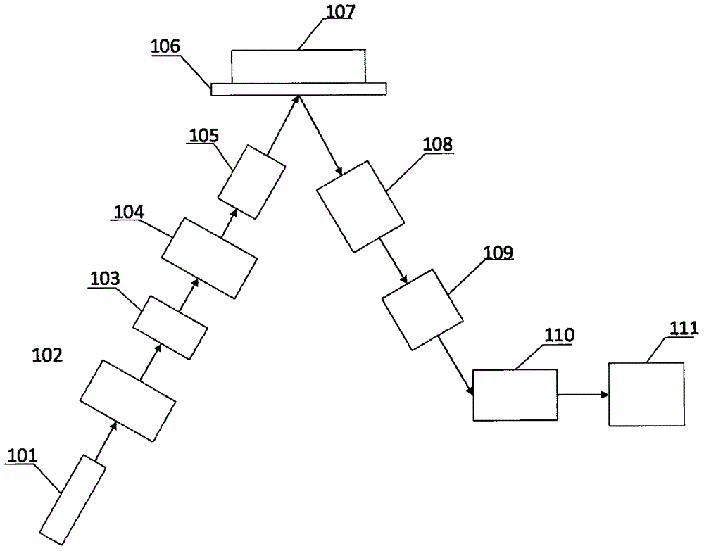
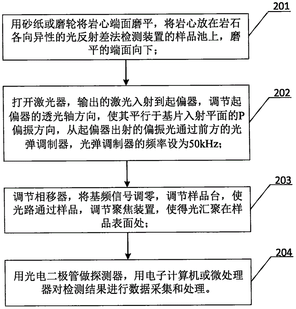
[0024] In order to effectively measure rock anisotropy, embodiments of the present invention provide a light reflection difference device and method for rock anisotropy detection. figure 1 It is a schematic diagram of the composition of the light reflection difference device for rock anisotropy detection in the embodiment of the present invention. Such as figure 1 As shown, the device of this embodiment includes an optical path of the device, a sample carrying device, a signal amplification device, and a data acquisition and processing system; the optical path of the...


PUM

PropertyMeasurementUnit
wavelengthaaaaaaaaaa

Abstract

The invention provides a device and method for detecting anisotropies of rocks by a light reflection difference method. The device comprises a device light path, a sample bearing device, a signal amplification device, and a data acquisition and processing system, wherein the device light path comprises an incident light path and an emergent light path; the incident light path comprises a laser device, a polarizer, a photoelastic modulator, a phase shifter and a focusing device; the emergent light path comprises a polarization analyzer and a photoelectric signal converter; and the photoelectric signal converter is a photoelectric diode and the signal amplification device is a lock phase amplifier. The device provided by the invention is simple in structure and easy to operate; and the signal-to-noise ratio is greatly improved, and the anisotropies of the rocks can be rapidly and accurately measured.

Description

technical field [0001] The invention relates to an optical instrument, in particular to a device and method for detecting rock anisotropy by light reflection difference. Background technique [0002] Rock anisotropy refers to the characteristics that the physical properties of natural rock mass vary with different spatial orientations, which are specifically manifested in the strength and deformation characteristics of rocks. Under the condition of natural rock mass, the basic reason for the anisotropy of the rock mass is that bedding, schistosing, interlayer and directional fracture (fault) system generally exist in the rock. [0003] At present, the research on rock anisotropy is mainly to study the wave velocity ratio characteristics of rock longitudinal and shear waves and resistivity anisotropy, etc., but the rock type restricts the development degree of wave velocity ratio anisotropy, and the research on rock resistivity anisotropy uses The multi-electrode combination...

Claims


Application Information

Patent Timeline
Patent Type & Authority Applications(China)
IPC IPC(8): G01N21/21
CPCG01N21/21
Inventor 许珊熊艳赵昆王金
Owner YANGTZE UNIVERSITY
Learn More