
Compulsory disturbance source positioning method based on power and frequency fluctuation phase

A technology of disturbance source location and frequency fluctuation, applied in fault locations, measuring devices, instruments, etc., can solve the problems of increasing the complexity of online monitoring and analysis of the system, cumbersome calculation of oscillation energy, and influence of calculation results, so as to reduce economic losses and social problems, reduced reliability, reduced complexity

Inactive Publication Date: 2016-07-06
SOUTHEAST UNIV
View PDF5 Cites 10 Cited by
  • Summary
  • Abstract
  • Description
  • Claims
  • Application Information

AI Technical Summary

Problems solved by technology

However, due to the forced oscillation of the system, the obtained data contains components and abnormal quantities not determined by the disturbance source, which may affect the calculation results
Moreover, the calculation of oscillation energy is cumbersome and takes a long time, which increases the complexity of online monitoring and analysis of the system

Method used


Image

  • Compulsory disturbance source positioning method based on power and frequency fluctuation phase
  • Compulsory disturbance source positioning method based on power and frequency fluctuation phase
  • Compulsory disturbance source positioning method based on power and frequency fluctuation phase

Examples


Embodiment Construction

[0043] The technical solution of the present invention will be further introduced below in combination with specific embodiments.

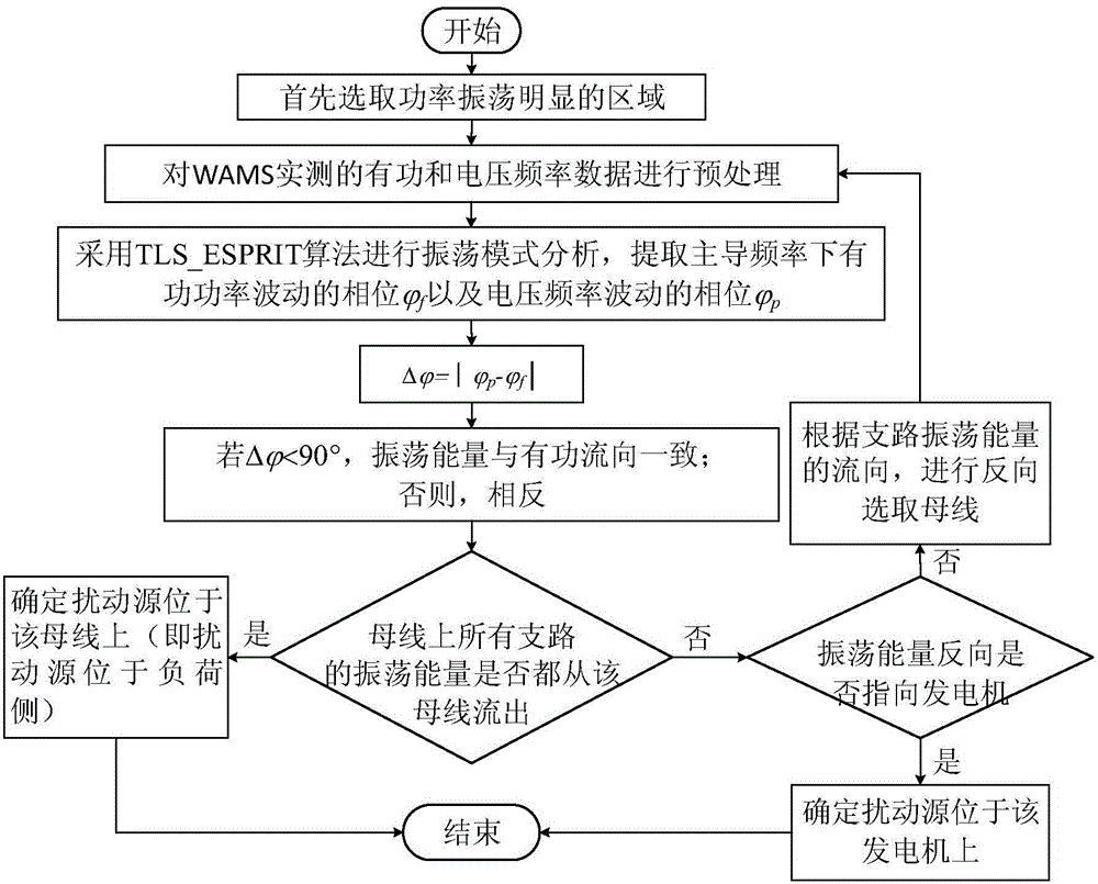
[0044] figure 1 It is a flow chart of the present invention, and the specific implementation of the present invention will be described below by taking the location of the disturbance source of a forced oscillation in an actual power grid as an example. The strong correlation local oscillation mode of a certain generator is obtained through small disturbance stability analysis, and the frequency is 0.8Hz. A continuous fluctuating load with an amplitude of 0.1 and a disturbance frequency of 0.8 Hz is applied to the load bus near the generator. At this time, the system undergoes forced oscillation.

[0045] The present invention comprises the following steps:

[0046] S1: According to the wide-area measurement system, that is, the WAMS system, the system power data obtained is to select the area where the branch power oscillation is obvious. The ...


PUM


Abstract

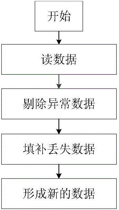
The invention discloses a forced disturbance source location method based on power and frequency fluctuation phase, which includes the following steps: S1: select an area with obvious power oscillation according to the system power data obtained by a wide-area measurement system; S2: select the bus in the area Frequency and branch power data are preprocessed; S3: Extract the dominant frequency of the forced oscillation, and obtain the signal amplitude and initial phase by the least square method to obtain the corresponding initial phase of fluctuation; S4: Calculate the bus frequency fluctuation and the connected The absolute value of the phase difference of the power fluctuation of the branch, formulate the criterion of the oscillation energy flow on the branch; S5: locate the disturbance source according to the criterion. The invention avoids the introduction of the whole network model to increase the analysis error and reduce the reliability, and greatly reduces the complexity of online monitoring and analysis.

Description

technical field [0001] The invention relates to the technical field of power system operation and control, in particular to a forced disturbance source location method based on power and frequency fluctuation phase. Background technique [0002] The rapid development of my country's power system has initially formed a situation of "power transmission from west to east, mutual supply from north to south, and national networking". While the reliability of the power grid is improved and the resource allocation is optimized, the low-frequency oscillation problem has also become a key issue affecting the safe and stable operation of the power system. Regarding the cause of low-frequency oscillations, in addition to the traditional view that the existence of negative damping in the system will cause low-frequency oscillations, more and more studies have found that continuous periodic small disturbances will cause forced oscillations in the system, and when the oscillation frequenc...

Claims


Application Information

Patent Timeline
Patent Type & Authority Applications(China)
IPC IPC(8): G01R31/08
CPCG01R31/088G01R31/086
Inventor 蒋平郑斌青冯双
Owner SOUTHEAST UNIV
Learn More