Rapid switch controller

A fast switch and control device technology, applied in the direction of electrical program control, sequence/logic controller program control, etc., can solve the problems of large loss, low reliability, and complicated maintenance, so as to shorten the maintenance time of equipment power outages and improve The effect of power supply reliability and simple logic structure

Inactive Publication Date: 2016-07-06
STATE GRID CORP OF CHINA +3
View PDF6 Cites 2 Cited by
  • Summary
  • Abstract
  • Description
  • Claims
  • Application Information

AI Technical Summary

Problems solved by technology

However, in the power distribution system with large capacity or above 10kV, compared with SSTS, the other two devices have the following obvious disadvantages: First, the cost is high, the loss is large, and the maintenance is complicated. If the UPS battery system needs to meet the large capacity output Requirements require large-capacity batteries or a large number of batteries to support, but the battery system needs regular maintenance and replacement; second, the structure is complex and the reliability is relatively low. It is applied to UPS and DVR in 10kV systems. However, the application of multi-series and parallel devices is often accompanied by other redundant circuit designs such as current sharing and voltage sharing, and strict requirements such as high power and identity of the drive circuit.
[0005] There is a fast switch controller invention patent 201310682409.1, which is composed of a backplane, a light input and light output board, a control board, a trigger board, a thyristor board and a power board; this invention patent is powerful, but there are many boards, if there is a fault, the fault point Relatively many, more difficult to troubleshoot

Method used


Image

  • Rapid switch controller
  • Rapid switch controller
  • Rapid switch controller

Examples


Embodiment Construction

[0017] Below in conjunction with embodiment the invention is described in further detail.

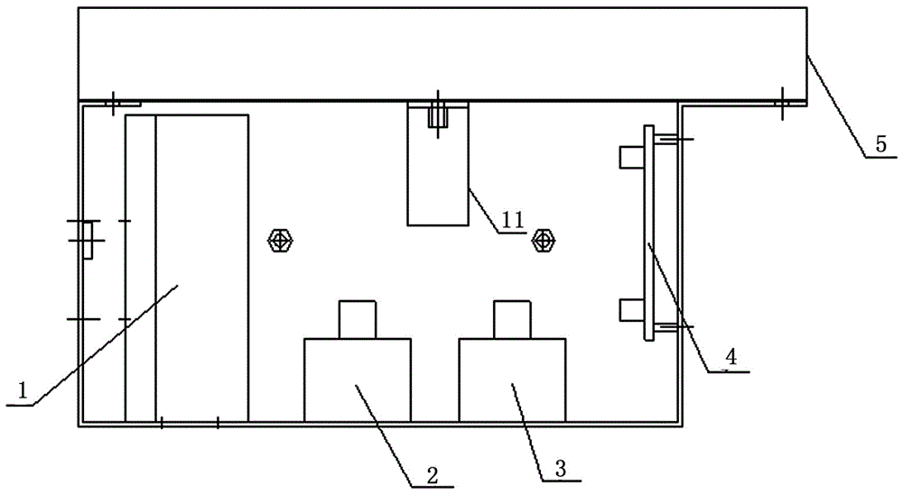
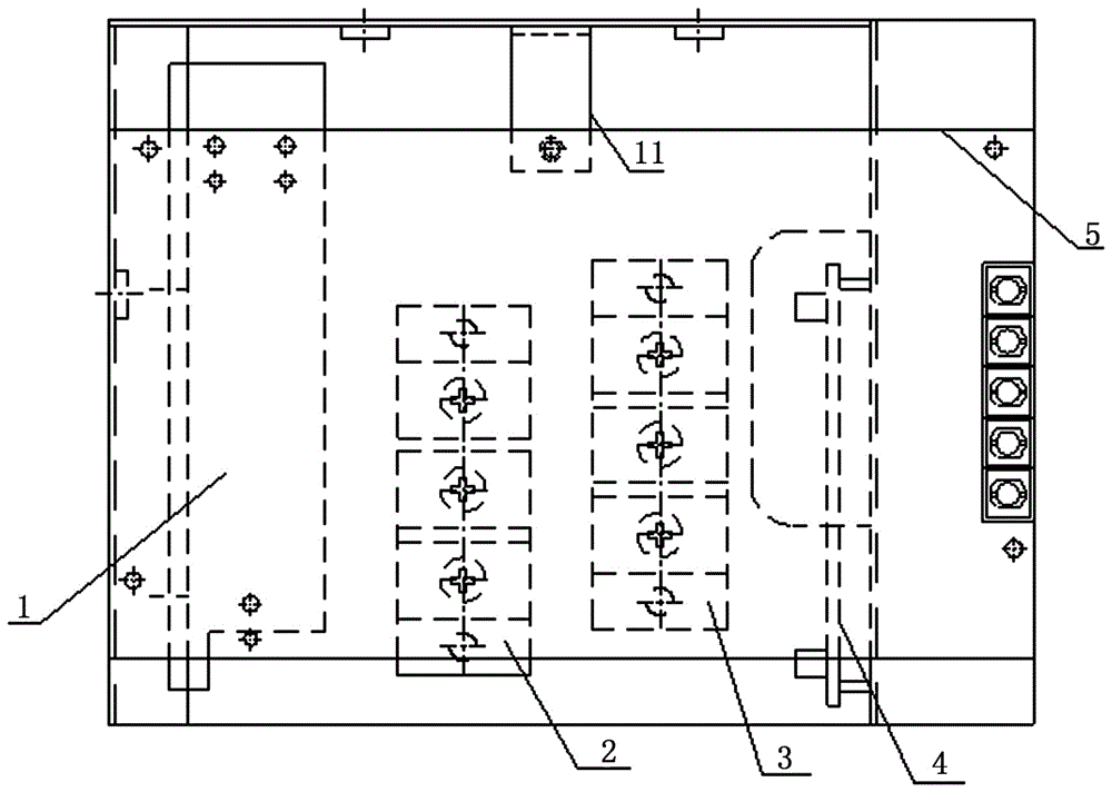
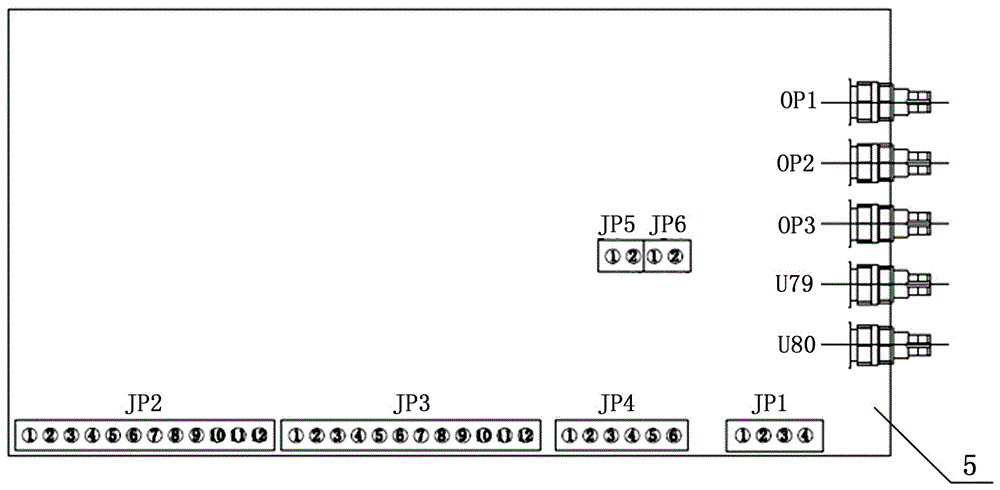
[0018] Figure 1 to Figure 5 It is a schematic diagram of an embodiment of the present invention. A fast switch control device of the present invention includes a chassis, an integrated switching power supply 1, an opening thyristor module 2, a closing thyristor module 3, a trigger board 4, and a control board 5. It is characterized in that: integrated The switching power supply 1, the opening thyristor module 2, the closing thyristor module 3, the trigger board 4, and the control board 5 are installed in a case in the fast switch cabinet; a control board 5 is arranged on the upper part of the case, and the case and the control board A control board bracket 11 is arranged between them; an integrated switching power supply 1, an opening thyristor module 2, a closing thyristor module 3, and a trigger board 4 are sequentially arranged inside the box; The signal cable JP4 is connected; the...


PUM


Abstract

A rapid switch controller comprises a cabinet, an integrated switch power supply, an opening thyristor module, a closing thyristor module, a trigger plate and a control plate, wherein the integrated switch power supply, the opening thyristor module, the closing thyristor module, the trigger plate and the control panel are installed in the cabinet in a rapid switchgear, the integrated switch power supply, the opening thyristor module, the closing thyristor module and the trigger plate are sequentially installed in the cabinet body, the integration switch power supply and the control panel are connected through a signal cable JP4, the control panel and the trigger plate are connected with each other through a Phoenix terminal JP5, a Phoenix terminal JP6 and a wire, the control panel is connected with an external controller through a fiber, and the trigger plate is connected with the external controller. The rapid switch controller has fewer board cards, less fault points, and simpler logic structures. Faults are easy to find, the power-off maintenance time of equipment is shortened, and the power supply reliability is substantially improved.

Description

technical field [0001] The invention relates to a control device, which belongs to the technical field of high-voltage power transmission and distribution system devices, in particular to a control device for fast switching. Background technique [0002] SSTS (Smart Solid State Transfer Switch) is a kind of power quality that is applied in the distribution network and monitors the power quality of sensitive loads in real time. When the voltage flicker, transient low, interruption, etc. It is an intelligent switching device for supplying conversion from one power supply to another. SSTS (Smart Solid State Transfer Switch) uses high voltage power thyristors and fast switches operating in parallel. When the power supply is connected, the power thyristor and the fast switch closing circuit are triggered synchronously, and the power supply is quickly connected by using the short conduction time of the power thyristor. After the switch is completely closed, the power thyristor is...

Claims


Application Information

Patent Timeline
Patent Type & Authority Applications(China)
IPC IPC(8): G05B19/04
CPCG05B19/04
Inventor 李晋峰张小龙孙浩张伟李鹏燕翚赵小英付永生赵瑞斌王轩郑青青何砚德王蓓蓓
Owner STATE GRID CORP OF CHINA
Why Eureka
Try Eureka