Unmanned aerial vehicle identification system and identification method thereof

A technology of unmanned aerial vehicle and identification system, which is applied in the field of identification system and identification of unmanned aerial vehicles, can solve the problems that unmanned aerial vehicles cannot distinguish target unmanned aerial vehicles, complex structure, etc., and achieve the effect of high recognition efficiency and simple structure

Active Publication Date: 2016-07-06
余江
11 Cites 31 Cited by

AI-Extracted Technical Summary

Problems solved by technology

This patent document integrates mobile phone communication modules such as 3G, GPRS and computer board integration modules into the flight control computer board through the mobile phone communication module and computer board integration module 211 in the flight control computer board setting unit 21. The electronic identification code setting module 212 sets an independent and unique electronic identification code for the UAV, communicat...

Method used

Signal transmission module 3 can be signal generator, and signal transmission module 3 is used for responding to identification request and sends the unique identification code corresponding to described unmanned aerial vehicle to described identification terminal 2, and described identification code is unmanned aerial vehicle The type identification code or machine serial code, which can be composed in any way, contains the identity information used to distinguish it from other drones, and further, it can also contain inf...

Abstract

The invention provides an unmanned aerial vehicle identification system and an identification method thereof. The identification system comprises a flight controller (1) which is arranged on an unmanned aerial vehicle and an identification terminal (2) which wirelessly communicates with the flight controller (1). The flight controller (1) comprises an information transmitting module (3). The identification terminal (2) comprises a wireless communication module (4) and a processing module (5). The processing module (5) transmits an identification request through the wireless communication module (4). The information transmitting module (3) responds to the identification request and transmits an identification code uniquely corresponding to the unmanned aerial vehicle to the identification terminal (2). The processing module (5) transmits a marking task request to the unmanned aerial vehicle corresponding to the identification code. The flight controller (1) performs a marking task according to the marking task request.

Application Domain

Technology Topic

Embedded systemUnmanned spacecraft +3

Image

  • Unmanned aerial vehicle identification system and identification method thereof
  • Unmanned aerial vehicle identification system and identification method thereof
  • Unmanned aerial vehicle identification system and identification method thereof

Examples

  • Experimental program(1)

Example Embodiment

[0034] The following detailed description is merely exemplary in nature and is not intended to limit application and usage. Furthermore, there is no intention to be bound by any expressed or implied theory presented in the above technical field, background, brief summary or the following detailed description. As used herein, the term "module" or "unit" refers to any hardware, software, firmware, electronic control component, processing logic and/or processor device, alone or in any combination, including without limitation: application specific integrated circuits (ASICs, ASICs, ASICs), Electronic circuits, processors executing one or more software or firmware programs, shared, dedicated or group sum memories, combinational logic circuits, and/or other suitable components that provide the described functionality. Furthermore, unless explicitly described to the contrary, the word "comprising" and its various variants should be understood to imply the inclusion of stated components but not the exclusion of any other components.
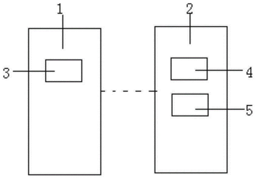
[0035] An unmanned aerial vehicle identification system described in the embodiment of the present invention is as follows: figure 1 As shown, the UAV identification system includes a flight controller 1 arranged on the UAV and an identification terminal 2 wirelessly communicating with the flight controller 1. The flight controller 1 includes an information sending module 3, and the The identification terminal 2 includes a wireless communication module 4 and a processing module 5, the processing module 5 sends an identification request through the wireless communication module 4, and the information sending module 3 responds to the identification request and sends a message unique to the unmanned aerial vehicle. The corresponding identification code is sent to the identification terminal 2, the processing module 5 sends an identification task request to the UAV corresponding to the identification code, and the flight controller 1 executes the identification task according to the identification task request.
[0036] Unmanned aerial vehicles can be various types of unmanned aerial vehicles, including fixed-wing, multi-rotor and other aircraft that can perform multi-degree-of-freedom activities in the airspace. The unmanned aerial vehicle 1 is preferably a multi-rotor unmanned aerial vehicle, and the unmanned aerial vehicle may include a flight controller 1 (AVC) or may also include a flight remote controller or other controller for sending flight instructions to the flight controller 1, so that The flight controller 1 controls the flight physics device to execute the flight according to the flight instruction.
[0037] The signal sending module 3 can be a signal generator, and the signal sending module 3 is used to respond to the identification request and send the identification code uniquely corresponding to the unmanned aerial vehicle to the identification terminal 2, and the identification code is the type identification of the unmanned aerial vehicle. code or machine serial code, the identification code, which can be composed of any method, contains identification information for distinguishing it from other drones, and further, it can also contain information that is of interest to the user or the management party, for example, the identification The code may be a machine certificate of the unmanned aerial vehicle, where the machine certificate includes at least one piece of information among the validity period of the unmanned aerial vehicle and the flight violation/violation situation. Of course, the above description is only an example, not a limitation. In one embodiment, the identification terminal 2 may be fixed on the ground, or may be installed on another unmanned aerial vehicle to further expand the identification range and enhance flexibility.
[0038] In one embodiment, the identification terminal 2 is a server or a cloud server. The identification terminal 2 is also a cloud server, which is a server cluster with many servers. Similar to a general computer architecture, the cloud server 2 consists of a processor, a hard disk, a memory, and a system bus. The cloud server 2 can provide simple, efficient, safe and reliable computing services with elastically scalable processing capabilities. The processor of the cloud server 2 may further include: CPU, RAM memory, operating system and application software. Responsible for multi-task scheduling, including wireless communication functions, memory read and write, and data processing. The hard disk or memory of the cloud server 2 may include a fast read/write SDD hard disk and a mobile read/write device that can be inserted into an SD card, which is mainly used to store the registered identification code data of the UAV and various application data, such as: registration The identification code and flight status information of the unmanned aerial vehicle, etc.
[0039] In one embodiment, the wireless communication module 4 includes at least one of wireless local area network communication devices, mobile communication network devices, stratospheric communication network devices and satellite network communication devices with different priorities, and the wireless communication module 4 establishes a wireless communication link with the UAV. Among them, the mobile communication network equipment is mainly composed of 2G/3G/4G wireless communication chipset, which is responsible for sending identification requests, identification task requests and receiving the identification code of the UAV sent by the information sending module 3 through the mobile communication network. The wireless local area network communication device can be one of Bluetooth, ZigBee or Wi-Fi modules. The wireless local area network communication device can establish short-range communication through the 2.4GHz communication frequency. In indoor or low-speed moving outdoor environments, this communication device is preferred to establish an unmanned aerial vehicle. Communication connection with the identification terminal 2 . The stratospheric communication network equipment generally uses helium-filled airships and balloons as the platform for placing the forwarding station. The height of the platform is 17km to 22km from the ground. When the unmanned aerial vehicle is flying in a large field, the stratospheric communication network equipment can be selected to establish and identify the unmanned aerial vehicle. Communication connection between terminals 2. The satellite network communication device uses the satellite communication channel to establish a communication connection between the UAV and the identification terminal 2, and generally uses the satellite network communication device as emergency communication when there is no other available wireless communication network.
[0040] In one embodiment, the wireless transmission network is selected according to the cost of the wireless network or the access speed of the wireless network. This application designs the following priority scheme, Wi-Fi network: priority is 0; 4G wireless network: priority is 1; 3G wireless network: priority is 2; stratospheric communication network: priority is 3; satellite communication network: priority is 4; When the signal strength is valid, the UAV will first select the Wi-Fi network as the wireless access network; when the Wi-Fi signal strength is invalid, the UAV will select the 4G network as the wireless access network second best; And so on.
[0041] In one embodiment, the wireless communication module 8 is further provided with a timer. The wireless communication module can time the communication connection.
[0042] In one embodiment, the identification terminal 2 may be a mobile phone or a pad. The identification terminal 2 used by the management party to inquire about the identity of the UAV and the UAV share the same communication link such as wifi, 4G, etc., and the identification terminal 2 can send an identification request to a certain range of UAVs by broadcasting, Taking the IP network as an example, an identification request can be sent to the broadcast address of 255.255.255.255, and all UAVs within the signal range can respond to the identification request.
[0043] In one embodiment, the information sending module 3 sends flight status information from the flight controller to the identification terminal 2, where the flight status information at least includes the orientation information, altitude information, and position of the UAV. One of information, speed information, acceleration information, and flight attitude information.
[0044] In one embodiment, the identification task is a lighting action or a hovering action of an unmanned aerial vehicle. The identification task may also be a combination of flight attitude and/or light action.
[0045] In one embodiment, the identification task is a light action, an unmanned aerial vehicle action or a signal action, wherein the light action is formed by flashing light-emitting units of multiple colors at different frequencies, for example, the light action is that the more and more flashing Fast red light or blue light that flashes more slowly, the light action can also be red light and blue light flashing at a predetermined frequency interval, etc. The unmanned aerial vehicle action can be any preset flight action, for example, the unmanned aerial vehicle The action can be hovering or nodding. For example, the unmanned aerial vehicle can make a nodding action of flying upward for 0.3 seconds, and then flying downward for 0.3 seconds. The signal action is to send a preset signal to the identification terminal. , for example, an unmanned aerial vehicle sends an acoustic signal or encoded information to an identification terminal.
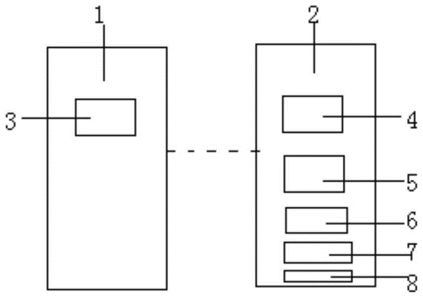
[0046] like figure 2 The shown unmanned aerial vehicle identification system includes a flight controller 1 arranged on the unmanned aerial vehicle and an identification terminal 2 wirelessly communicating with the flight controller 1, and the flight controller 1 includes an information sending module 3. The identification terminal 2 includes a wireless communication module 4, a processing module 5 and a monitoring module 6. When the unmanned aerial vehicle enters a predetermined airspace, the monitoring module 6 sends an alarm message to the processing module 5 and the processing module 5 is in the A predetermined communication channel sends an identification request, the information sending module 3 responds to the identification request and sends an identification code and flight status information uniquely corresponding to the unmanned aerial vehicle to the identification terminal 2, and the processing module 5 sends the information to the identification terminal 2. The unmanned aerial vehicle corresponding to the identification code sends an identification task request, and the flight controller 1 executes the identification task according to the identification task request.
[0047] When the manager of the predetermined airspace finds through the monitoring module 6 that an unmanned aerial vehicle is approaching or entering the predetermined area, it sends an identification request through the identification terminal, and the information sending module 3 responds to the identification request and sends an identification uniquely corresponding to the unmanned aerial vehicle. code and flight status information such as heading, altitude, speed, bearing, etc. to the identification terminal 2. Since there may be multiple unmanned aerial vehicles (such as legal users and illegal users) within the coverage area of ​​the identification terminal 2, when the above flight information cannot help When the management party quickly distinguishes each UAV, the processing module 5 sends an identification task request to the UAV corresponding to the identification code, and the flight controller 1 executes the identification task according to the identification task request. For example, UAVs can respond by flashing the lights of the UAV in a fixed manner or by hovering or other indicative actions, thereby helping managers identify the UAVs that need to be managed.
[0048] In one embodiment, the identification terminal 2 further includes a storage module 7 and a verification module 8, the storage module 7 stores the registered identification code data; the verification module 8 verifies whether the received identification code is in the in the registered identification code data. Through the verification of the verification module, the identification system can further distinguish legal UAVs from illegal UAVs.
[0049] In one embodiment, the processing module 5 may compile, organize or analyze the data in the storage module 7 to perform comparative analysis of the data. The processing module 5 may include a general purpose processor, a digital signal processor, an application specific integrated circuit ASIC, a field programmable gate array FPGA, analog circuits, digital circuits, combinations thereof, or other processors known or later developed. The storage module 7 may be a volatile memory or a non-volatile memory. The memory module 7 may include one or more of read only memory ROM, random access memory RAM, flash memory, electronically erasable programmable read only memory EEPROM or other types of memory.
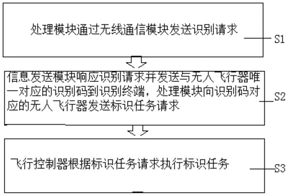
[0050] see image 3 Shown is a schematic diagram of steps of a method for identifying an unmanned aerial vehicle according to an embodiment of the present invention, and the steps are as follows.
[0051] In the first step S1, the processing module 5 sends an identification request through the wireless communication module 4;
[0052] In the second step S2, the information sending module 3 responds to the identification request and sends an identification code uniquely corresponding to the unmanned aerial vehicle to the identification terminal 2, and the processing module 5 sends the identification code to the unmanned aerial vehicle corresponding to the identification code. The human aircraft sends an identification task request;
[0053] In the third step S3, the flight controller 1 performs the identification task according to the identification task request.
[0054] In this method, the identification system can dynamically identify the unmanned aerial vehicle flying in the air, and the flying characteristics of the unmanned aerial vehicle such as small size, low height and high density cannot be carried out by the air traffic control system of traditional aircraft. Management, etc., it is proposed to use the identification terminal 2 to send identification requests within a predetermined range, and further send identification task requests through identification codes.
[0055] see Figure 4Shown is a schematic diagram of steps of a method for identifying an unmanned aerial vehicle according to another embodiment of the present invention, and the steps are as follows.
[0056] In the first step S1, the monitoring module 6 sends alarm information to the processing module 5 and the processing module 5 sends an identification request on a predetermined communication channel;
[0057] In the second step S2, the information sending module 3 responds to the identification request and sends the identification code uniquely corresponding to the UAV and the flight status information to the identification terminal 2, and the verification module 8 verifies the received Whether the identification code is in the registered identification code data;
[0058] In the third step S3, when the verification is passed, the processing module 5 sends an identification task request to the UAV corresponding to the identification code, and the flight controller 1 executes the identification task according to the identification task request.
[0059] In this method, the unmanned aerial vehicle entering the predetermined airspace is detected in advance through the monitoring module, the identification terminal 2 is used to send an identification request within a predetermined range, the unmanned aerial vehicle is verified by receiving the identification code and the flight status information, and further, an identification task request is sent. , the unmanned aerial vehicle further identifies the unmanned aerial vehicle by combining the identification task of flight elements and light/flight attitude.
[0060] Although the embodiments of the present invention have been described above with reference to the accompanying drawings, the present invention is not limited to the above-mentioned specific embodiments and application fields, and the above-mentioned specific embodiments are only illustrative and instructive, rather than restrictive . Those of ordinary skill in the art can also make many forms under the inspiration of this specification and without departing from the scope of protection of the claims of the present invention, which all belong to the protection of the present invention.

PUM

no PUM

Description & Claims & Application Information

We can also present the details of the Description, Claims and Application information to help users get a comprehensive understanding of the technical details of the patent, such as background art, summary of invention, brief description of drawings, description of embodiments, and other original content. On the other hand, users can also determine the specific scope of protection of the technology through the list of claims; as well as understand the changes in the life cycle of the technology with the presentation of the patent timeline. Login to view more.

Similar technology patents

Classification and recommendation of technical efficacy words

  • Simple structure
  • Improve recognition efficiency

Microlithographic projection exposure apparatus

InactiveUS20050068499A1Simple structureReliable and low-maintenance operationProjectorsPhotomechanical exposure apparatusCamera lensPhysics
Owner:CARL ZEISS SMT GMBH
Why Eureka
Try Eureka