
Patterned structural substrate and optoelectronic semiconductor element

A patterned substrate and optoelectronic semiconductor technology, which is applied in the manufacture of semiconductor devices, electrical components, semiconductor/solid-state devices, etc., can solve the problems of limitation, increase the efficiency of light extraction, and reduce the area of ​​flat parts, so as to reduce manufacturing costs, The effect of improving epitaxy yield and improving electrical performance

Inactive Publication Date: 2016-07-06
LUCEMITEK
View PDF4 Cites 13 Cited by
  • Summary
  • Abstract
  • Description
  • Claims
  • Application Information

AI Technical Summary

Problems solved by technology

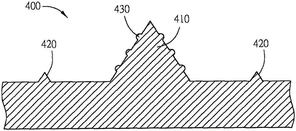
However, if Figure 1C As shown, the patterned sapphire substrate 400 produced by the known process can only increase the roughness in the form of fine protrusions 430 on the raised microstructure pattern 410 to reduce the area of ​​the overall flat part. However, The structure of the fine protrusions 430 formed on the microstructure pattern 410 is substantially limited in its contribution to increasing the light extraction efficiency.

Method used


Image

  • Patterned structural substrate and optoelectronic semiconductor element
  • Patterned structural substrate and optoelectronic semiconductor element
  • Patterned structural substrate and optoelectronic semiconductor element

Examples


Embodiment Construction

[0029] The patterned substrate and optoelectronic semiconductor elements according to preferred embodiments of the present invention will be described below with reference to the relevant drawings, wherein the same elements will be described with the same reference numerals. The illustrations of all the embodiments of the present invention are only schematic, and do not represent actual sizes and ratios. In addition, the orientations "up" and "down" in the following embodiments are only used to represent relative positional relationships. Furthermore, "on", "over", "under" or "under" that an element is formed on another element may include that one element is in direct contact with another element in an embodiment, or may also include that one element is in contact with another element. There are other additional elements between one element so that one element does not have direct contact with another element.

[0030] Please refer to figure 2 As shown, it is a partial per...


PUM


Abstract

The invention discloses a patterned structural substrate which includes a substrate, a microstructure and a nanostructure. The substrate has a surface. The microstructure is configured on the surface of the substrate. The nanostructure is formed on the surface of the substrate or the microstructure. The nanostructure includes a nano-protruding part or a nano-recessed part. The invention also discloses an optoelectronic semiconductor element having the patterned structural substrate.

Description

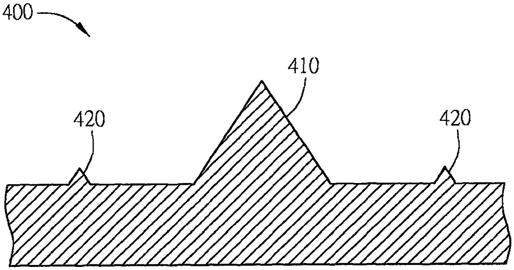
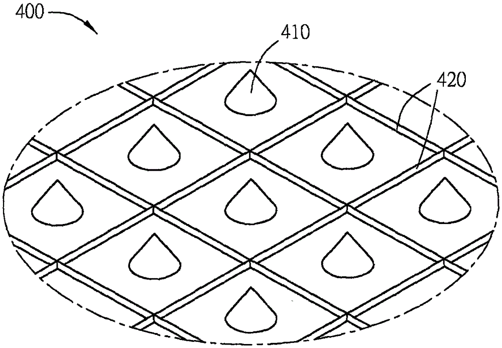
technical field [0001] The invention relates to a patterned substrate and an optoelectronic semiconductor element, in particular to a patterned substrate and an optoelectronic semiconductor element capable of improving photoelectric efficiency. Background technique [0002] Optoelectronic semiconductor devices have been widely used in various products in people's daily life, such as lighting, vehicles, display devices, communication industry or computers and other fields. [0003] The known optoelectronic semiconductor elements are provided with multiple microstructures on the surface of the substrate, and the microstructure patterns of the optoelectronic semiconductor elements form a patterned structural substrate (Patterned Structural Substrate, PSS), also known as a patterned substrate, as described below Pattern the substrate. [0004] Please refer to Figure 1A to Figure 1C As shown, they are structural schematic diagrams of hybrid patterned sapphire substrates (hybrid...

Claims


Application Information

Patent Timeline
IPC IPC(8): H01L33/22H01L51/50H01L31/0236
CPCH01L31/02366H01L33/22H10K77/10H10K50/00Y02E10/549
Inventor 邱正宇李俊亿陈俊宏
Owner LUCEMITEK
Learn More