Method for carrying out 10kV charged wire connecting operation by CO2 laser cable peeling device

A technology of CO2 and lead wires, which is applied in the direction of cable installation device, cable installation, overhead line/cable equipment, etc., can solve the problems of high risk factor, impossibility of popular use, current overload and heat generation, etc., and meet the requirements of safety and manufacturability Requirements, realize remote all-round monitoring, and increase the effect of reliability

Active Publication Date: 2016-07-06
ANSHAN POWER SUPPLY COMPANY OF STATE GRID LIAONING ELECTRIC POWER COMPANY +2
View PDF6 Cites 4 Cited by
  • Summary
  • Abstract
  • Description
  • Claims
  • Application Information

AI Technical Summary

Problems solved by technology

[0004] The domestic 10kV power supply line live connection operation is a routine high-voltage live operation. It has gone through four technical stages: insulating gloves, insulating tools, insulating bucket trucks and robots. The first three stages are all manual live work. In the threat of electric field, the risk factor is high, which is likely to cause personal injury and death accidents. However, the live connection operation of the robot has no stress feeling when operating the lead wire cutting insulation skin tool, and the mechanical tool often scratches the metal cable core, so it cannot be widely used.
[0005] There is also a technical form of insulation piercing lead clip, which is also a direction for the development of live connection technology at present, but the puncture contact piece is limited by the material, and in the high voltage level live connection operation, it is difficult to face the insulation protection layer of high voltage cables. The density and thickness of the puncture contact piece and the contact area of ​​the cable metal core are not easy to control, and it is very easy to cause current overload and heat due to poor contact, and even fire accidents

Method used


Image

  • Method for carrying out 10kV charged wire connecting operation by CO2 laser cable peeling device
  • Method for carrying out 10kV charged wire connecting operation by CO2 laser cable peeling device
  • Method for carrying out 10kV charged wire connecting operation by CO2 laser cable peeling device

Examples


Embodiment Construction

[0040] The specific embodiment of the present invention will be further described below in conjunction with accompanying drawing:

[0041] A use of CO 2 The laser cable peeling device performs 10kV live wire connection operation method, including the following steps:

[0042] 1) Operators should wear insulating and protective equipment, and provide reliable insulation and shielding for charged and grounded bodies within the scope of work;

[0043] 2) Make sure that the line to be connected has no ground short circuit and is well insulated;

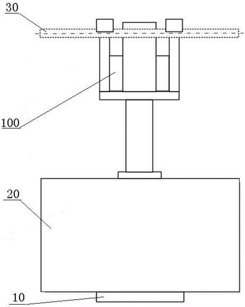
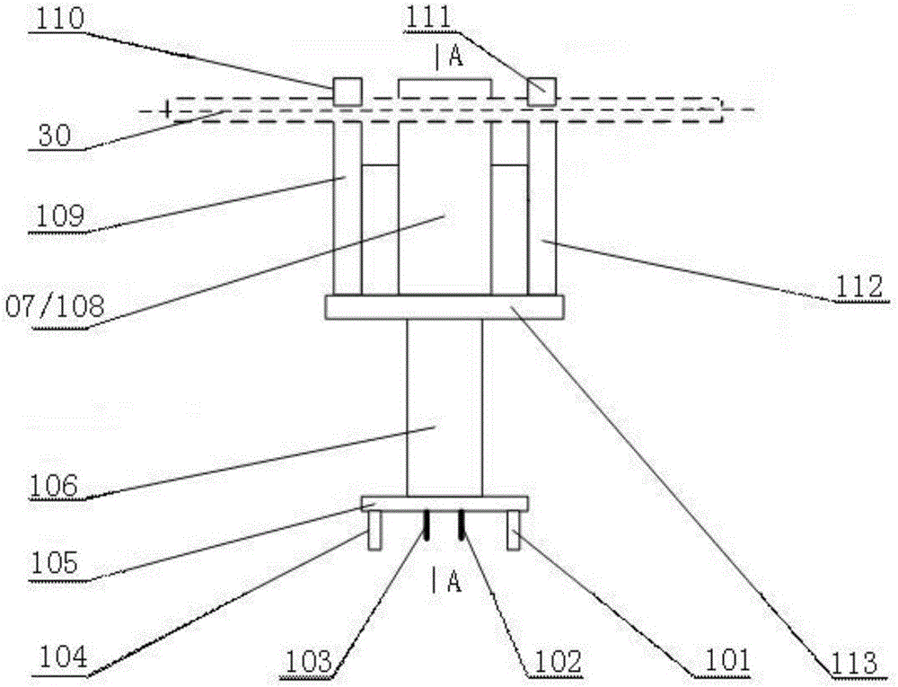
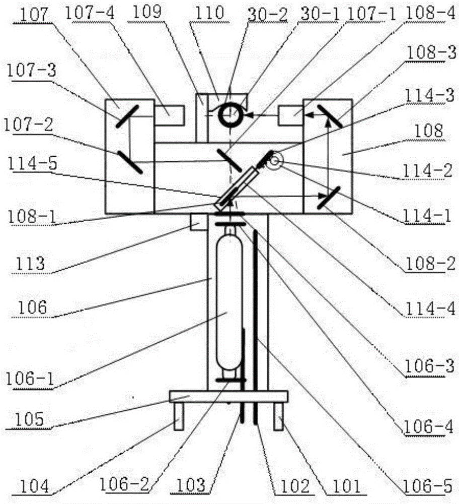
[0044] 3) CO 2 The laser cable peeling device 100 is lifted to the operating point of the live lead wire by an insulated bucket truck, and the CO 2 The laser cable peeling device 100 is suspended on the live wire 30, and its cutting laser beam emission positions are respectively located on both sides of the live wire 30;

[0045] 4) start CO 2 The laser cable peeling device 100 cuts out "H"-shaped incisions on both sides of the live w...


PUM


Abstract

The invention relates to a method for carrying out 10kV charged wire connecting operation by a CO2 laser cable peeling device. The CO2 laser cable peeling device is suspended on a live wire; H-shaped notches are cut out at two sides of the live wire respectively; the H-shaped notches at two sides are accurately butted and then form two annular notches at two sides and two coherent longitudinal notches between the two annular notches on the live wire; a cut insulating sheath is peeled off from the live wire; one end of a drainage wire is locked by a lock bar; the drainage wire is sent to a live wire connection position; a round mouth screw type drainage wire clamp is suspended on the live wire with a drainage wire clamp operating rod; a bolt is tightened; and the drainage wire clamp and the wire are tightly fixed. Online peeling is carried out on the live wire by the CO2 laser cable peeling device; a metal cable core is not damaged; the peeling efficiency is high; the notches are accurate; and the reliability of 10kV charged wire connection is greatly improved.

Description

technical field [0001] The invention relates to an operation method for live work, in particular to a method using CO 2 Laser cable peeling device for 10kV live wire connection operation method. Background technique [0002] Power supply is the basic guarantee for maintaining social production and residents' life, and is an important pillar of national economic development. However, with the rapid development of the national economy and the continuous improvement of people's living standards, the power grid system has gradually become larger, and the expansion of the power grid has become more frequent, requiring frequent maintenance, new equipment installation, power connection and other construction in large quantities. As far as the 10kV power supply line is concerned, due to the long power supply line and the increase in power supply users, a power outage will cause immeasurable losses, especially in residential areas with dense high-rise buildings, the power outage inf...

Claims


Application Information

Patent Timeline
Patent Type & Authority Applications(China)
IPC IPC(8): H02G1/02H02G1/12
CPCH02G1/02H02G1/128
Inventor 张涛张朝龙刘君高振江黄耀阳李叶军
Owner ANSHAN POWER SUPPLY COMPANY OF STATE GRID LIAONING ELECTRIC POWER COMPANY
Why Eureka
Try Eureka