Paint mist capturing water cyclone

A water cyclone and paint mist technology, applied in chemical instruments and methods, separation of dispersed particles, use of liquid separation agents, etc., can solve problems affecting the capture effect of paint mist, blockage of high-pressure equipment, accumulation of paint mist, etc., and achieve high water quality Purification performance, increase the total amount, and avoid the effect of paint mist accumulation

Inactive Publication Date: 2016-07-13
AEROSPACE KAITIAN ENVIRONMENTAL TECH CO LTD
View PDF7 Cites 1 Cited by
  • Summary
  • Abstract
  • Description
  • Claims
  • Application Information

AI Technical Summary

Problems solved by technology

[0004] Although the above methods have a good reference value in theory, there are inevitable limitations in practical engineering applications.
Installing a baffle in the middle of the hydrocyclone is conducive to the atomization of water, but the paint mist always moves downward under the action of gravity, and setting the baffle in the vertical direction of movement will easily cause the accumulation of paint mist; in engineering applications, the overflow flow mainly comes from paint. For the circulating water after fog deposition, pressurization equipment or high-pressure nozzles must be used to pressurize the overflow flow. Since the paint mist particles in the overflow flow cannot achieve 100% deposition, the fine paint mist particles are very easy to cause blockage of high-pressure equipment ; On the one hand, the method of reducing the radius of the middle part of the hydrocyclone to form a pressure gradient distribution will cause the paint mist to accumulate at the variable diameter, and at the same time, the originally stable turbulent flow of the system is easily disturbed due to the formation of the pressure gradient, thus affecting the capture of paint mist Effect

Method used


Image

  • Paint mist capturing water cyclone
  • Paint mist capturing water cyclone
  • Paint mist capturing water cyclone

Examples


Embodiment

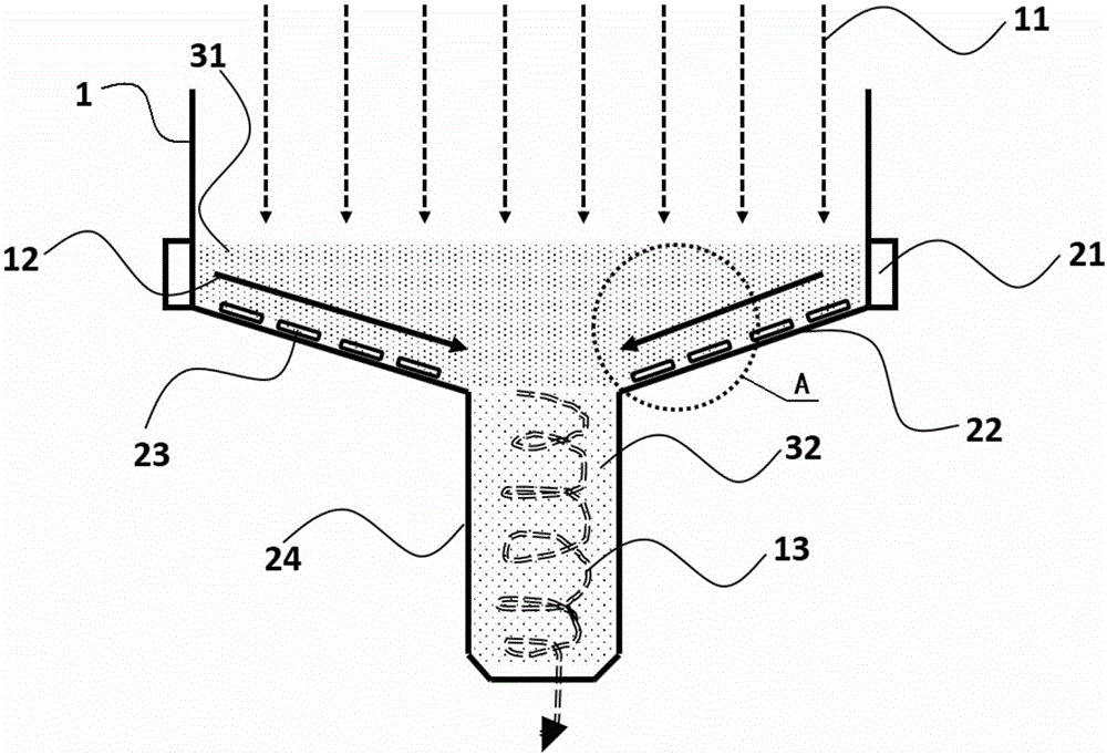
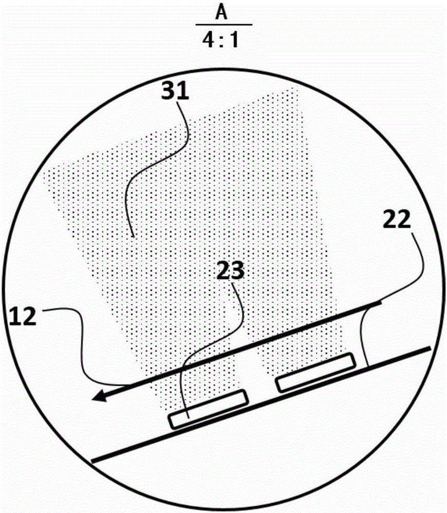
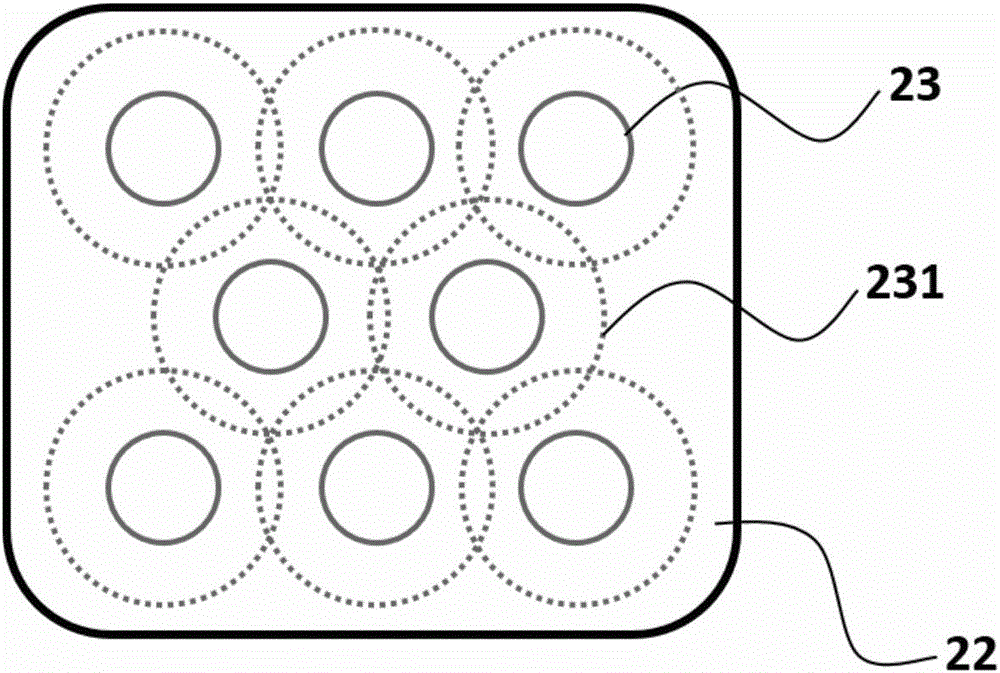
[0032] see figure 1 , the paint mist capture water cyclone in the illustration includes a cylinder 1 and a water cyclone 24. The cylinder 1 in the illustration is a straight cylinder, and the bottom of its inner cavity is an impact plate 22 with an inverted conical bottom. The middle of the impact plate 22 The position is connected to the water cyclone 24, and the inner cavity of the cylinder and the water cyclone are connected to each other; an overflow 21 is set on the outer wall of the cylinder 1, and the overflow flow 12 outside the cylinder flows to the impact plate through the overflow, and the impact plate 22 is laid with an oscillating slice 23, such as figure 2 As shown, part of the overflow water flow 12 forms an oscillating water mist 31 through high-frequency oscillation.

[0033] In this embodiment, the impact plate 22 is an inverted conical structure with high surroundings and low center, wherein the overflow port 21 is arranged around the height of the impact ...


PUM


Abstract

The invention discloses a paint mist capturing water cyclone. The paint mist capturing water cyclone comprises a barrel and a water cyclone barrel, wherein an impacting plate is arranged at the bottom of an inner cavity of the barrel and connected with the water cyclone barrel, and the inner cavity of the barrel is communicated with the water cyclone barrel; overflow ports are formed in the outer wall of the barrel, and overflowed water outside the barrel flows onto the impacting plate via the overflow ports; vibration pieces are laid on the impacting plate; the effective vibration range formed by the vibration pieces covers the impacting plate comprehensively, the overflowed water entering the overflow ports is atomized into nanoscale particles, excitation water mist is formed in the water cyclone barrel, so that the total quantity of the water mist is increased, contact between paint mist and the water mist is enhanced, the capturing capacity of the water cyclone for the paint mist is significantly enhanced, and the problem of deposition of the paint mist on the impacting plate is further solved. The water cyclone has the advantages of outstanding performance and simple structure, can effectively avoid accumulation of the paint mist and has the broad application prospect.

Description

technical field [0001] The invention belongs to paint mist treatment equipment, in particular to a paint mist capture water cyclone. Background technique [0002] In the coating industry, there are problems such as the extensive use of organic solvents for spraying and poor sealing conditions in the production environment. The paint mist produced by it has teratogenic, carcinogenic, and mutagenic effects, causing many harms to the human body and the ecological system. At present, the methods of paint mist treatment include wet filtration (use water curtain or water mist to capture paint mist), dry filtration (mesh filter paint mist), centrifugal separation (use the centripetal force generated by rotation to separate paint mist from air), collision Interception (the paint mist collides on the surface of the baffle and aggregates into large particles), adsorption-dissolution method (use the adsorption material to absorb the paint mist and then wash it off with a solvent, so th...

Claims


Application Information

Patent Timeline
Patent Type & Authority Applications(China)
IPC IPC(8): B01D47/00
CPCB01D47/00
Inventor 何曦叶明强
Owner AEROSPACE KAITIAN ENVIRONMENTAL TECH CO LTD
Why Eureka
Try Eureka