Part cleaning tank

A technology for cleaning tanks and parts, which is applied in the field of parts cleaning. It can solve the problems of uneconomical, low cleaning efficiency, and easy dirty hands, and achieve the effect of not easy to dirty hands, high cleaning efficiency, and prolonging the service life.

Inactive Publication Date: 2016-07-13
DONGGUAN QINGMAITIAN DIGITAL TECH
View PDF8 Cites 4 Cited by
  • Summary
  • Abstract
  • Description
  • Claims
  • Application Information

AI Technical Summary

Problems solved by technology

However, for factories that use a certain type of machine to produce other products, it is not necessary to clean a large number of parts, but to clean and maintain parts in a small number of machines as needed. If a special assembly line operation parts cleaning tank is arranged in the factory building , it is very wasteful and uneconomical
In the prior art, people often use manual work to clean the parts one by one, the cleaning efficiency is low, and the hands are easy to get dirty, and the storage of cleaning oil is also a big problem

Method used


Image

  • Part cleaning tank
  • Part cleaning tank
  • Part cleaning tank

Examples


Embodiment Construction

[0019] The specific embodiment of the present invention will now be described in detail in conjunction with the accompanying drawings.

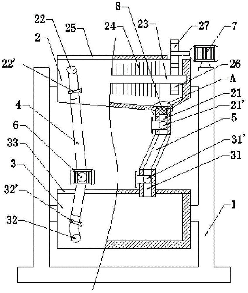
[0020] Such as figure 1 As shown, the parts cleaning tank of the present invention includes a support 1, a cleaning barrel 2 and an oil storage barrel 3, the cleaning barrel 2 and the inch oil barrel are located on the support 1, and the oil storage barrel 3 is arranged under the cleaning barrel 2, and the cleaning The bottom of the barrel 2 is provided with an oil outlet 21, the top of the cleaning barrel 2 is provided with an oil inlet 22, the bottom of the oil storage barrel 3 is provided with an oil outlet 32, and the top of the oil storage barrel 3 is provided with an oil inlet 31, The oil outlet 21 of the cleaning barrel 2 is directly connected with the oil inlet 31 of the oil storage barrel 3 through the oil discharge pipe 5 , and the oil outlet 32 ​​of the oil storage barrel 3 is connected with the oil inlet 22 of the cleaning barrel...


PUM

PropertyMeasurementUnit
angleaaaaaaaaaa

Abstract

The invention discloses a part cleaning tank. The part cleaning tank comprises a cleaning cylinder and an oil storage cylinder located on a support, wherein an oil outlet in the bottom of the cleaning cylinder is directly connected with an oil inlet in the upper portion of the oil storage cylinder through an oil drainage pipe, an oil outlet in the bottom of the oil storage cylinder is connected with an oil inlet in the upper portion of the cleaning tank through an oil inlet pipe, and an oil well pump is arranged in the middle of an oil inlet pipeline to be used for pumping oil in the oil storage cylinder into the cleaning tank; a long shaft is arranged in the cleaning cylinder and penetrates through the cleaning cylinder, the two ends of the long shaft are inserted into the left side and right side of the inner wall of the cleaning cylinder, a gear is fixedly arranged at the right end of the long shaft, a driving wheel driven by a motor is arranged above the gear, the driving wheel is meshed with the gear to drive the long shaft to rotate, the motor is located outside the cleaning tank, and a layer of bristles adhere to the outer surface of the long shaft. The part cleaning tank is suitable for automatic cleaning of a small batch of parts, cleaning efficiency is high, hands do not get dirty easily, cleaning oil can be recycled, occupied space is small, and service life is long.

Description

technical field [0001] The invention relates to the field of parts cleaning, in particular to a parts cleaning tank. Background technique [0002] Parts are the basic elements of machine composition. In parts processing factories, there are often parts cleaning tanks for assembly line operations, which have a large structure, high cost, and a large floor area. However, for factories that use a certain type of machine to produce other products, it is not necessary to clean parts in large quantities, but to clean and maintain parts in a small number of machines as needed. If a special assembly line operation parts cleaning tank is arranged in the factory building , it seems very wasteful and uneconomical. In the prior art, people often use manual work to clean the parts one by one. The cleaning efficiency is low, and the hands are easy to get dirty. The storage of cleaning oil is also a big problem. Contents of the invention [0003] The present invention aims to provide ...

Claims


Application Information

Patent Timeline
Patent Type & Authority Applications(China)
IPC IPC(8): B08B3/08B08B1/04C09D133/00C09D163/00C09D7/12C09D5/08
CPCB08B3/08B08B1/04C09D5/08C09D7/61C09D7/63C09D133/00
Inventor 刘丽蓉
Owner DONGGUAN QINGMAITIAN DIGITAL TECH
Why Eureka
Try Eureka