A combination fixing device for high temperature pipelines

A technology for fixing devices and pipelines, which is applied in pipeline protection, pipeline support, and pipeline protection through heat insulation, etc. It can solve problems such as support failure, fixed support failure, and large thermal stress, so as to improve the ability to withstand moments and improve reliability. and safety, the effect of reducing stress levels

Active Publication Date: 2018-11-23
CHENGUANGDONGLUO BELLOWS CO LTD NANJING
View PDF12 Cites 0 Cited by
  • Summary
  • Abstract
  • Description
  • Claims
  • Application Information

AI Technical Summary

Problems solved by technology

Due to the large pipe diameter and high medium temperature, the conventional welded fixed bracket will cause very large thermal stress. Excessive stress can easily lead to cracking of the weld and failure of the bracket, which poses a great threat to the safe operation of the system.
[0003] At present, the conventional welded fixing brackets of the process pipelines of petrochemical plants are prone to cracks in the welds with high stress levels and the parent metal parts of the process pipelines after a period of operation at high temperatures. The cracks will not only lead to failure of the fixing brackets but also It will lead to cracking of the process pipeline, which will cause serious consequences for the leakage of the process medium
[0004] In the prior art, there is no fixed support for high-temperature and large-diameter pipelines that can withstand large thrust and torque and meet long-term operation

Method used


Image

  • A combination fixing device for high temperature pipelines
  • A combination fixing device for high temperature pipelines
  • A combination fixing device for high temperature pipelines

Examples


Embodiment Construction

[0029] The present invention will be further described below in conjunction with accompanying drawing:

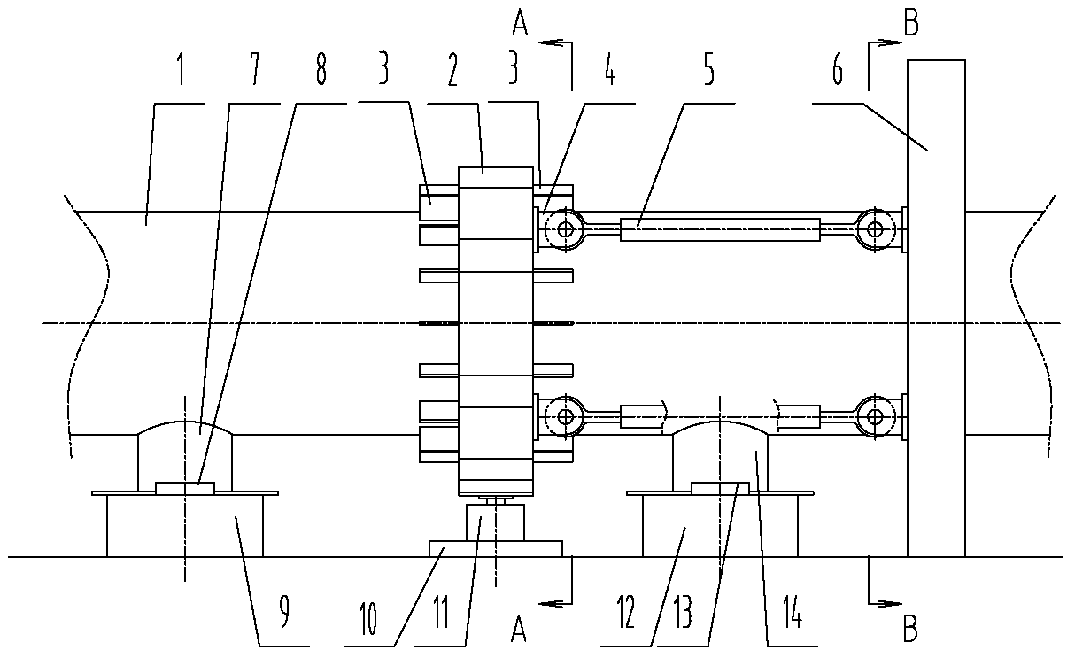
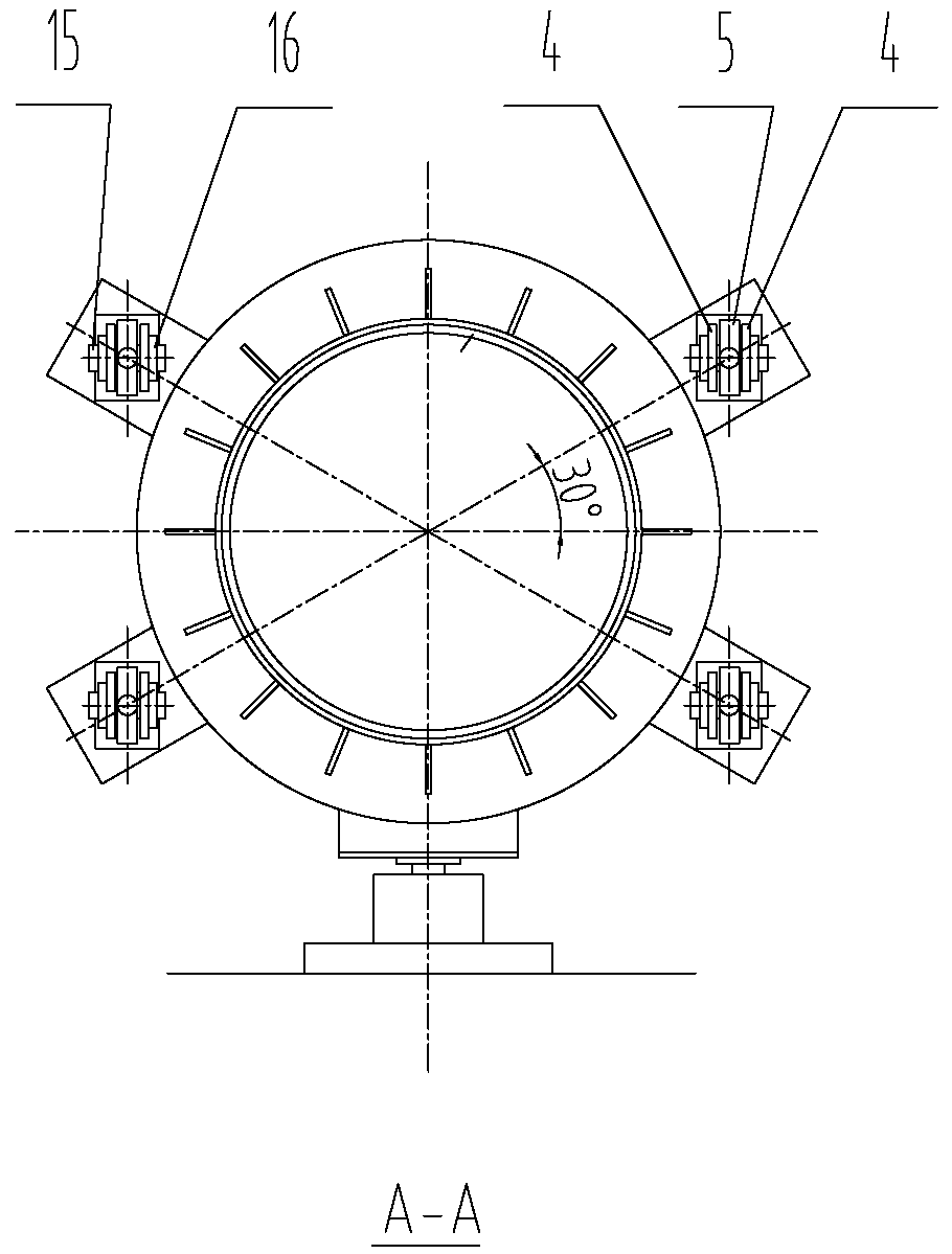
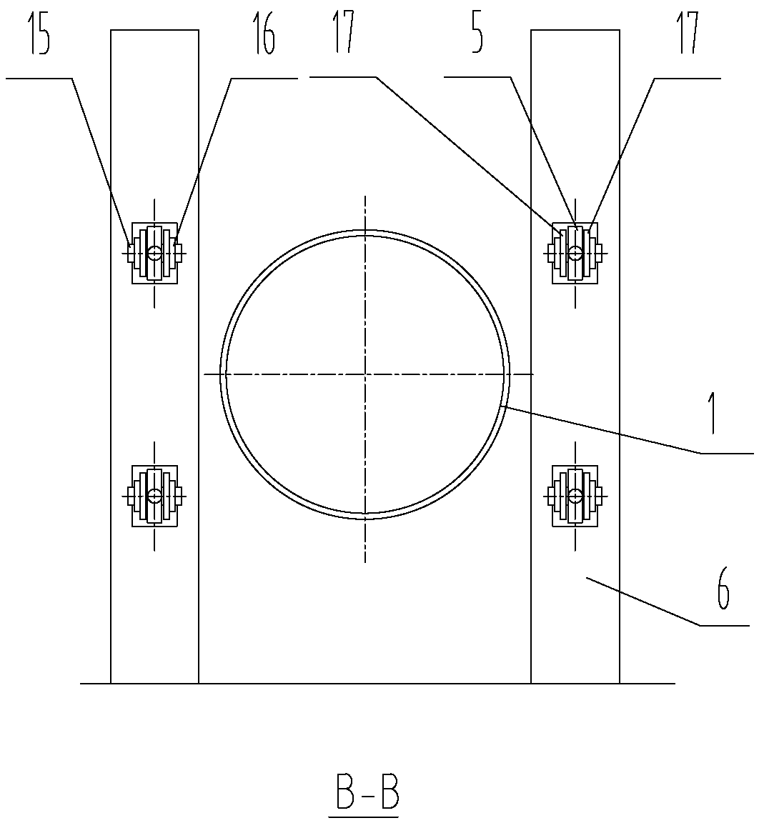
[0030] Such as figure 1 As shown, the present invention includes a pipeline 1, and a floating structure 2 is arranged outside the place where the pipeline 1 needs to be fixed. The floating structure 2 is composed of two box-type semi-rings with a rectangular cross section, and the inside of the rectangular frame of the two semi-rings is filled along the circumference. The heat insulation material wrapped by steel wire is connected by bolts and nuts to form an integral ring. The floating structure 2 is set on the pipe 1. There is a space between the inner diameter of the floating structure 2 and the outer diameter of the pipe 1 that is greater than the radial expansion of the pipe 1. gap. Weld evenly distributed baffles 3 along the circumference of the pipeline 1. If the pipeline 1 is only under one-way force during system operation, the baffles 3 are only arranged on the l...


PUM


Abstract

The invention discloses a high-temperature pipeline combining and fixing device. Structurally, a floating structure which is arranged outside a pipeline in a sleeving manner is mounted at a part to be fixed, of the pipeline; a baffle plate which is fixed on the outer wall of the pipeline is arranged on a bearing side of the floating structure; one side of the floating structure is connected with a support frame arranged on two sides of the pipeline through pull rod components; linear displacement constraint along the pipeline in the axis direction is achieved through the pull rod combined structure, and the axial force of the pipeline can be born. In addition, a guide bracket is mounted at the bottom of the pipeline, and radial rotation of the pipeline is limited by the anti-rotating baffle plate on a guide support base below the guide bracket. The purpose of fixing the pipeline is achieved, and meanwhile thermal expansion of the high-temperature pipeline is not constrained, so that the stress level of a connecting part can be greatly reduced, the probability that attachment weld and process pipelines are cracked in long-term high-temperature operation is effectively avoided, and the requirements of full-load long-term security operation of process pipelines of high-temperature large-aperture petrochemical plants can be completely met.

Description

technical field [0001] The invention relates to a fixing structure of a large-diameter high-temperature pipeline. Background technique [0002] With the development of the national economy, petrochemical plants are developing toward large scale. The process and design conditions of process pipelines are not only harsh, but the design temperature is high, reaching 600-750°C, and the caliber is also increasing with the scale of the plant. In order to ensure the normal operation of the process piping system, the piping needs to be supported and fixed in place to ensure the stability and safety of the system. Due to the large pipe diameter and high medium temperature, the conventional welded fixed bracket will cause very large thermal stress. Excessive stress can easily lead to cracking of the weld and failure of the bracket, which poses a great threat to the safe operation of the system. [0003] At present, the conventional welded fixing brackets of the process pipelines of p...

Claims


Application Information

Patent Timeline
Patent Type & Authority Patents(China)
IPC IPC(8): F16L3/10F16L3/205F16L59/02F16L59/07
CPCF16L3/10F16L3/205F16L59/02F16L59/07
Inventor 牛玉华李亮周命生
Owner CHENGUANGDONGLUO BELLOWS CO LTD NANJING
Why Eureka
Try Eureka