
Light splitting model test device capable of measuring transparent spoil internal three dimensional displacement field

A model test device, transparent soil technology, applied to measuring devices, optical devices, instruments, etc., can solve problems such as failure to realize three-dimensional observation, and achieve the effect of simple structure, easy to grasp, and convenient operation

Inactive Publication Date: 2016-07-13
NORTH CHINA UNIV OF WATER RESOURCES & ELECTRIC POWER
View PDF3 Cites 20 Cited by
  • Summary
  • Abstract
  • Description
  • Claims
  • Application Information

AI Technical Summary

Problems solved by technology

[0004] The experimental device for studying transparent soil based on PIV technology is currently only limited to the use of a single-speed laser surface light source, and only studies the strain and displacement field of a certain plane inside the soil, failing to achieve true three-dimensional observation

Method used


Image

  • Light splitting model test device capable of measuring transparent spoil internal three dimensional displacement field
  • Light splitting model test device capable of measuring transparent spoil internal three dimensional displacement field

Examples


Embodiment Construction

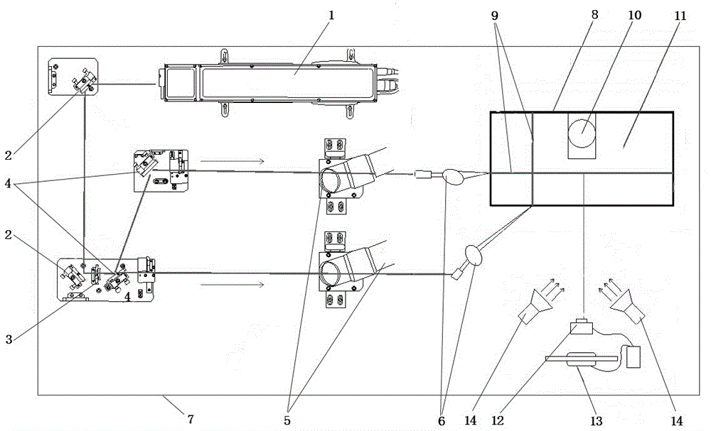
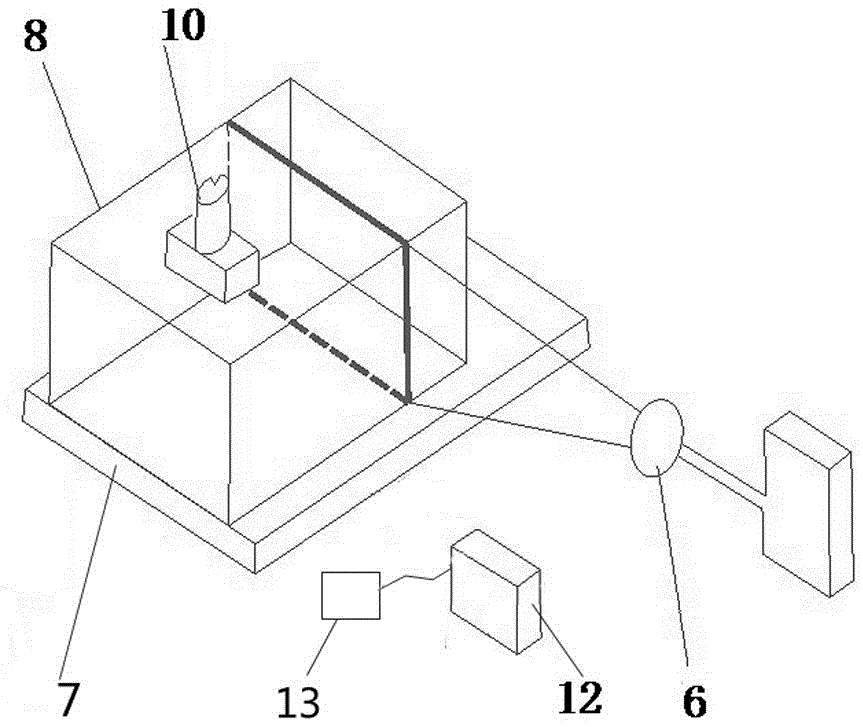
[0027] Such as figure 1 , 2 As shown, a spectroscopic model test device that can measure the three-dimensional displacement field of transparent soil, which includes an optical platform and a laser spectroscopic system set on the optical platform, a transparent soil model test device and a PIV test system;

[0028] The laser beam splitting system includes a solid-state laser 1, a 45° total mirror 2, a half-wave plate 3, a polarizer 4, and a lens group 6. The laser light emitted by the solid laser 1 is directed to the 45° total mirror I and passes through the 45° total mirror I. Reflected to the 45° total mirror II, and then emitted from the 45° total mirror II, passed through the half-wave plate 3 to the parallel polarizer I and polarizer II, polarized by the polarizer 4 and then directed toward the lens group 6, lens Group 6 turns a single laser beam into a surface beam;

[0029] The transparent soil model test equipment includes a model box 8 and a test loading device 10 and a tr...


PUM


Abstract

The invention discloses a light splitting model test device capable of measuring a transparent spoil internal three dimensional displacement field, and a test method thereof. The light splitting model test device comprises an optical platform and a laser light splitting system, a transparent soil model test device and a PIV test system which are all arranged on the optical platform. The test device can split a single beam laser source into double beam laser sources, form vertical planar light beams through a lens assembly, and vertically slice soil samples. The device can truly realize monitoring of a spoil body internal three dimensional deformation field in a spoil body natural state; referred instruments have simple structures, and are convenient to operate and easy to master.

Description

Technical field [0001] The invention relates to a model test device applied to geotechnical engineering tests, in particular to a spectroscopic model test device that can measure the three-dimensional displacement field inside transparent soil. Background technique [0002] In geotechnical engineering, the bearing characteristics of deep and shallow foundations and settlement calculation methods have been studied a lot, but there are few studies on the interaction between soil and structure, and the mechanism of interaction between soil and structure remains to be Further research. However, due to the non-transparency of traditional soil, it is impossible to continuously observe and record the deformation of any point in the soil caused by the settlement of the shallow foundation. [0003] With the emergence of transparent soil in the 20th century and its application in physical simulation experiments of geotechnical engineering, non-invasive measurement of soil internal deformati...

Claims


Application Information

Patent Timeline
Patent Type & Authority Applications(China)
IPC IPC(8): G01B11/16
CPCG01B11/162
Inventor 姜彤张俊然任淼史颜玲张昕李洪军
Owner NORTH CHINA UNIV OF WATER RESOURCES & ELECTRIC POWER
Learn More