Fiber-optic gyroscope eigenfrequency measuring equipment and application thereof

A technology of fiber optic gyroscope and eigenfrequency, which is applied in the direction of measuring devices and instruments, can solve the problems of insufficient intuitive measurement, complicated measurement process, and insufficient precision, and achieve the effect of convenient transportation and carrying, high measurement accuracy, and organized layout

Inactive Publication Date: 2016-07-13
上海傲世控制科技股份有限公司
View PDF6 Cites 8 Cited by
  • Summary
  • Abstract
  • Description
  • Claims
  • Application Information

AI Technical Summary

Problems solved by technology

However, this measurement method is not intuitive enough, the me

Method used


Image

  • Fiber-optic gyroscope eigenfrequency measuring equipment and application thereof
  • Fiber-optic gyroscope eigenfrequency measuring equipment and application thereof
  • Fiber-optic gyroscope eigenfrequency measuring equipment and application thereof

Examples


Example Embodiment

[0037] The present invention will be described in detail below with reference to the drawings and specific embodiments. This embodiment is implemented on the premise of the technical solution of the present invention, and a detailed implementation mode and specific operation process are given, but the protection scope of the present invention is not limited to the following embodiments.
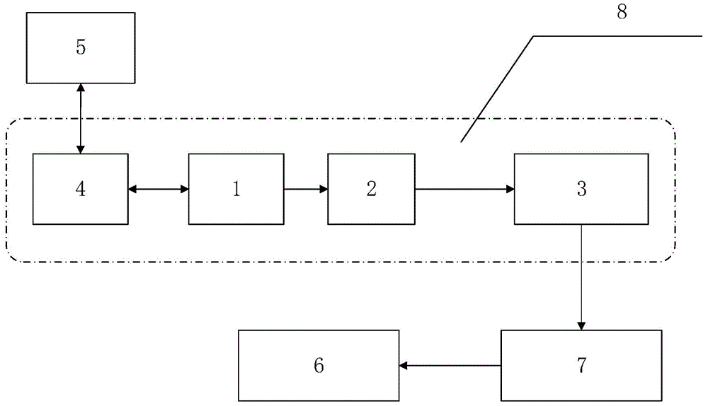
[0038] An optical fiber gyroscope intrinsic frequency measurement equipment, such as figure 1 As shown, it includes a digital-to-analog converter 2 and an operational amplifier circuit 3 connected to each other, and also includes a digital square wave signal generating component and an oscilloscope 6. The operational amplifier circuit 3 is connected to the input end of the fiber optic gyroscope 7, and the output end of the fiber optic gyroscope 7 is connected to The oscilloscope 6 is connected, and the digital square wave signal generating component is connected to the digital-analog converter 2....


PUM


Abstract

The invention relates to fiber-optic gyroscope eigenfrequency measuring equipment and application thereof.The equipment comprises a digital-to-analog converter, an operational amplifier circuit, a digital square signal generation module and an oscilloscope.The operational amplifier circuit is connected with an input end of a fiber-optic gyroscope, an output end of the fiber-optic gyroscope is connected with the oscilloscope, and the digital square signal generation module is connected with the digital-to-analog converter.Compared with the prior art, the fiber-optic gyroscope eigenfrequency measuring equipment and application thereof have the advantages that by adoption of the oscilloscope, whether an output waveform of the fiber-optic gyroscope is a comb-like waveform or not is judged to determine whether a frequency of a modulation square wave is an eigenfrequency or not, and high measurement precision is achieved.

Description

technical field [0001] The invention relates to a fiber optic gyroscope performance debugging technology, in particular to a fiber optic gyroscope eigenfrequency measuring device and its application. Background technique [0002] The fiber optic gyroscope is an angular rate sensor based on the Sagnac effect, and is currently the main sensor used to determine the spatial motion attitude of moving objects. The Sagnac effect means that two beams of light propagate towards each other in a closed fiber ring. When the fiber ring rotates, a Sagnac phase shift proportional to the rotation angular rate occurs between the two light waves. The time for light to propagate in the fiber ring is the eigenperiod τ, and the eigenfrequency is: [0003] 1 2 τ [0004] When the modulation frequency of the FOG is equal to the eigenfrequency of the FOG, the performance of the FOG is optimal. However, there is currently a lack of high-prec...

Claims


Application Information

Patent Timeline
IPC IPC(8): G01C25/00
Inventor 李阳李佳程彭以新甘晨君黄芳
Owner 上海傲世控制科技股份有限公司
Why Eureka
Try Eureka