Onsite calibrating device for asynchronous electric vibration testing system

A technology of electrodynamic vibration and test system, which is applied in vibration test, measuring device, machine/structural component test, etc. It can solve the problems of violent shaking of cables, integration error, and inability to accurately obtain acceleration amplitude, etc., so as to avoid measurement uncertainty Degree, improve the effect of measurement accuracy

Inactive Publication Date: 2016-07-13
SHANGHAI PRECISION METROLOGY & TEST RES INST
View PDF5 Cites 14 Cited by
  • Summary
  • Abstract
  • Description
  • Claims
  • Application Information

AI Technical Summary

Problems solved by technology

[0005] 1) When the table vibrates under coupling conditions, the table of the test system will tilt, and the acceleration sensor will also tilt accordingly. Therefore, the direction of the acceleration amplitude measured by the acceleration sensor changes, and the acceleration amplitude of the determined direction cannot be accurately obtained;
[0006] 2) When the acceleration sensor is used for measurement, the signal output by the sensor needs to be transmitted to the signal acquisition system through a low-noise cable. When the table is tilted and vibrated, it is easy to cause severe shaking of the cable, thereby affecting the measurement accuracy of the acceleration sensor;
[0007] 3) The acceleration sensor can directly measure the acceleration amplitude of the test system, and cannot directly obtain the vibration velocity and displacement. When the integration is performed to obtain the vibration velocity and displacement, an integration error will be introduced

Method used


Image

  • Onsite calibrating device for asynchronous electric vibration testing system
  • Onsite calibrating device for asynchronous electric vibration testing system
  • Onsite calibrating device for asynchronous electric vibration testing system

Examples


Embodiment Construction

[0024] In order to make the above objects, features and advantages of the present invention more comprehensible, the present invention will be further described in detail below in conjunction with the accompanying drawings and specific embodiments.

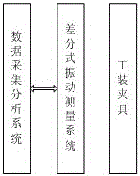
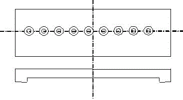
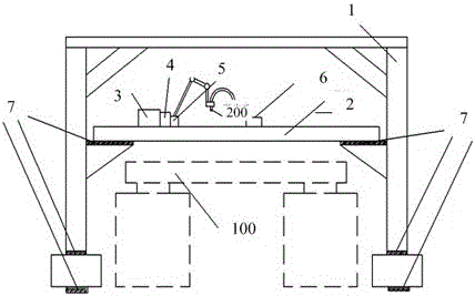
[0025] Such as Figures 1 to 3 As shown, the present invention provides an on-site calibration device for an asynchronous electrodynamic vibration test system 100, including:

[0026] The differential Doppler laser vibrometer system is used to measure the vibration amplitude. Preferably, the differential Doppler laser vibrometer system is used to output two lasers, and the two lasers measure the distance between two points. Relative vibration displacement, velocity and acceleration. Here, the principle of laser Doppler is adopted. Laser Doppler vibration measurement is to obtain the vibration velocity and displacement of the measured object by measuring the frequency shift caused by the optical path change between the laser light ...


PUM


Abstract

The invention provides an onsite calibrating device for an asynchronous electric vibration testing system. The device achieves the non-contact measurement of the testing system through the preparation of a tool clamp. The device achieves the direct measurement of the vibrating speed and displacement through employing a differential-type Doppler laser vibration measurement system, and the vibration of a table cannot affect an output signal of the device. The device improves the measurement accuracy of the vibrating speed and displacement of the testing system, can obtain the vibration amplitude in a needed measurement direction through adjusting the incident direction of laser to the needed measurement direction, and is not affected by the tilting of the table in a vibrating process. In other words, the device can obtain the vibration amplitude in the determined direction, and the designed tool clamp can carry out the coarse tuning and fine tuning of the measurement position of a laser probe, thereby enabling the laser to precisely reach the position to be measured, and achieving the accurate tracing of a measurement value of the testing system.

Description

technical field [0001] The invention relates to the field of calibration of mechanical environment test equipment, in particular to an on-site calibration device for an asynchronous electrodynamic vibration test system. Background technique [0002] The asynchronous electrodynamic vibration test system is a dual shaking table and dual control system, and has a special hydraulic hinge-type angle compensation device and a linear guide-type displacement compensation device to ensure that the simulation test system realizes rotational vibration on the transverse centerline of the common table and limits the other Rotational vibration occurs in the direction; through the precise positioning of the mounting screw holes on the common table and each shaking table, it is ensured that the transverse centerline of the common table coincides with the center line of the two shaking tables, so that the simulation test system can simulate the bending vibration generated by the missile. Tha...

Claims


Application Information

Patent Timeline
Patent Type & Authority Applications(China)
IPC IPC(8): G01H9/00G01M7/02
CPCG01H9/004G01M7/025
Inventor 田晓涛田芳怡罗晓平
Owner SHANGHAI PRECISION METROLOGY & TEST RES INST
Why Eureka
Try Eureka