

Automatically-positioned power unit test bench
A power unit and automatic positioning technology, which is applied in the testing of mechanical components, testing of machine/structural components, testing of machine gears/transmission mechanisms, etc., can solve problems such as adverse effects of power units, and achieve good contact and uniform force Effect
Active Publication Date: 2016-07-13
ANHUI HELI CO LTD
View PDF8 Cites 0 Cited by
- Summary
- Abstract
- Description
- Claims
- Application Information
AI Technical Summary
Problems solved by technology
In this case, after the wheel of the power unit is under pressure, the force that does not pass through the center of the wheel is likely to generate additional partial load force, which makes the force on the gears in the gear box of the power unit inconsistent with the actual working conditions, and the noise of the test is difficult. In line with the actual situation, it is also easy to have adverse effects on the power unit
Method used
View moreImage
Smart ImageViewing Examples

Examples
Embodiment
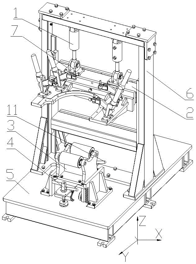
[0042] see figure 1 . An automatic positioning power unit test bench includes a test bench support, an assembly tool 2 and a carrying device 3 .
Login to View More PUM
 Abstract
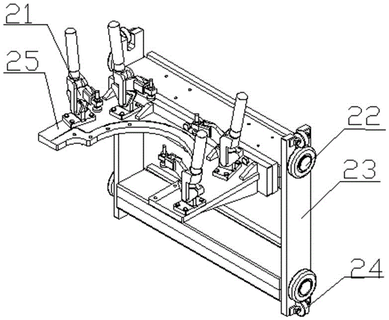
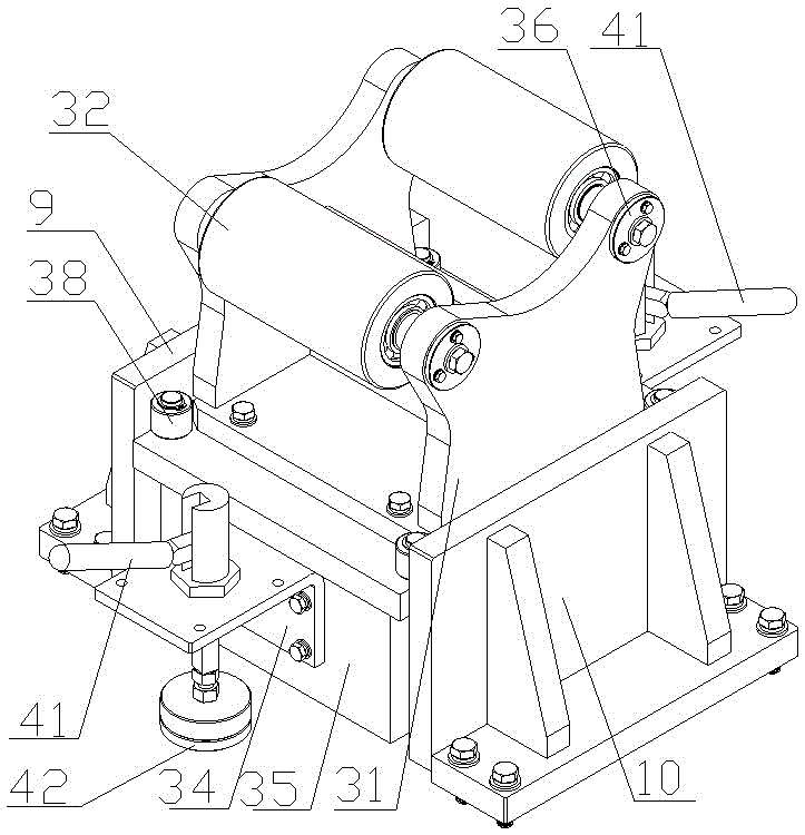
The invention relates to an automatically-positioned power unit test bench, which comprises a test bench support, an assembly tool and a bearing device, wherein the test bench support is composed of a flat plate-shaped base and a door frame-type frame; the frame is uprightly arranged on the top surface of the base; two oil cylinders are parallelly suspended in a channel steel frame; the tail part of each oil cylinder is connected onto the upper crossbeam of the channel steel frame; the piston rod end of the oil cylinder is hinged onto an upper plane of an upper crossbeam of a mounting pulley of the assembly tool; twalking rollers and adjusting rollers of the mounting pulley are respectively arranged in channel steel frame notches; the front part of the mounting frame is provided with a semi-arc notch connected onto the front side of the upper crossbeam of the mounting pulley; four quick clamping devices are arranged around the semi-arc notch on a rib plate upper plane of the mounting fame; and the central position of the arc is corresponding to that between a front bearing roller and a rear bearing roller of a roller supporting frame. The automatically-positioned power unit test bench has the beneficial effects that relative positions between a bearing device and a tested piece are kept consistent, and rolling friction is realized between wheels of the tested piece and the bearing mechanism.
Description
technical field [0001] The invention relates to a simulated power unit test bench, in particular to a power unit test bench capable of automatic positioning. Background technique [0002] For electric forklifts, it is necessary to develop a power unit detection test bench, which can test the noise and running resistance of the power unit under high speed and load conditions, and the test bench can simulate the force state of the power unit in the whole vehicle. [0003] When the whole vehicle is running at high speed, the power unit of the vehicle is subjected to the force of the weight of the whole vehicle, and its direction is vertically downward. It should also go through the center of the wheel. When the existing forklift power unit is tested, the test bench seldom simulates this stress state, and no test bench can accurately pass the downward force through the center point of the wheel. In this case, after the wheels of the power unit are under pressure, the force tha...
Claims
Login to View More Application Information
Patent Timeline
 Patent Type & AuthorityApplications(China)
IPC IPC(8): G01M13/02
CPCG01M13/027
Inventor施文静
OwnerANHUI HELI CO LTD