
Directional positioning energy-saving control circuit for blowing and suction cleaning machine

A directional positioning, energy-saving control technology, applied in the direction of adjusting electric variables, control/regulation systems, textiles and papermaking, etc., can solve the problems of not being able to control the stop position of the cleaning machine well, high energy consumption, and difficulty in ensuring the cleaning effect, etc.

Active Publication Date: 2017-07-04
ANHUI HUAMAO TEXTILE
View PDF6 Cites 0 Cited by
  • Summary
  • Abstract
  • Description
  • Claims
  • Application Information

AI Technical Summary

Problems solved by technology

However, at present, the current blowing and suction cleaning machines in the market have poor energy-saving effect and high energy consumption during continuous operation, and cannot well control the stop position of the cleaning machine during intermittent operation, making it difficult to ensure the cleaning effect.

Method used


Image

  • Directional positioning energy-saving control circuit for blowing and suction cleaning machine

Examples


Embodiment Construction

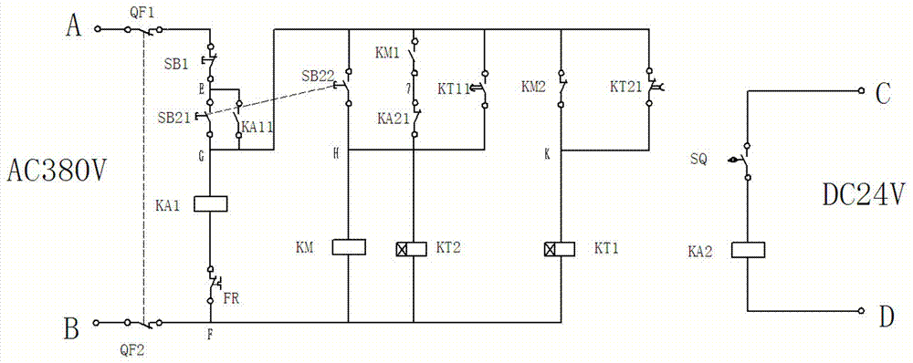
[0013] The directional positioning energy-saving control circuit of a blowing suction cleaning machine of the present invention will be further described in detail below with reference to the accompanying drawings.

[0014] Depend on figure 1 It can be seen that a directional positioning energy-saving control circuit for a blowing and suction cleaning machine of the present invention includes a strong current port A and a strong current port B connected to an external 380V AC power supply, a weak current port C and a weak current port D connected to an external 24V DC power supply, and an intermediate relay KA1 to start. , Running contactor KM, delayed start time relay KT1, delayed disconnection time relay KT2, positioning intermediate relay KA2, bipolar switches QF1 and QF2, stop button SB1 and start button SB2. In this embodiment, the strong current port A is connected in series with the bipolar switch QF1 and the stop button SB1 to the connection port E in sequence. After t...


PUM


Abstract

The invention discloses a directional positioning energy-saving control circuit of an air blowing and suction cleaning machine. The directional positioning energy-saving control circuit comprises a strong-current port A and a strong-current port B of an external 380V alternating-current power supply, a weak-current port C and a weak-current port D of an external 24V direct-current power supply, a switch-on intermediate relay KA1, an operation contactor KM, a delay start time relay KT1, a delay switch-off time relay KT2, a positioning intermediate relay KA2, a double-pole switch QF1, a double-pole switch QF2, a stop button SB1 and a start button SB2. According to the technical scheme, the circuit has the advantages of being simple in structure and convenient and reliable to operate, can effectively control operation and stop time and the stop position of the air blowing and suction cleaning machine according to different product varieties and cleaning conditions, is convenient and reliable to operate, and guarantees the cleaning effect.

Description

technical field [0001] The invention relates to a control circuit, in particular to a directional positioning energy-saving control circuit for a blowing and suction cleaning machine. Background technique [0002] The blowing and suction cleaning function can be used in conjunction with various specifications and types of roving, spun yarn, winding, doubling, double twisting, open-end spinning, weaving and other textile machinery that need blowing and suction cleaning. It can remove flying flowers and inhibit the accumulation of dust, reduce the phenomenon of broken ends and yarn defects and weaving defects caused by the adhesion of flying flowers, improve product quality, and can replace manual automatic tour cleaning work, reduce the cleaning workload of workers and increase the number of car blocking machines. It is an ideal equipment for civilized production environment and improvement of production efficiency. However, the current blowing and suction cleaning machines ...

Claims


Application Information

Patent Timeline
Patent Type & Authority Patents(China)
IPC IPC(8): D01H11/00
CPCG05F1/10
Inventor 舒畅杨春
Owner ANHUI HUAMAO TEXTILE
Learn More