Signal-triggered startup low voltage rectifying and filtering type drive system for automatic clamping

A signal-triggered and automatic clamping technology, applied in output power conversion devices, conversion of AC power input to DC power output, electrical components, etc. Improves versatility and versatility

Inactive Publication Date: 2016-07-13
CHENGDU CLAY STAR TECH CO LTD
View PDF0 Cites 0 Cited by
  • Summary
  • Abstract
  • Description
  • Claims
  • Application Information

AI Technical Summary

Problems solved by technology

[0003] The purpose of the present invention is to overcome the current system structure of automatic control clamping is relatively complicated and the cost is relatively high, and the system used for automatic control clamping is often specially made for a certain tool or workpiece, which is not convenient for general use , to provide a low-voltage rectification and filtering drive system that is not only simple in structure, but also low in cost, and convenient for general-purpose signal triggering and starting for automatic clamping

Method used


Image

  • Signal-triggered startup low voltage rectifying and filtering type drive system for automatic clamping
  • Signal-triggered startup low voltage rectifying and filtering type drive system for automatic clamping
  • Signal-triggered startup low voltage rectifying and filtering type drive system for automatic clamping

Examples


Embodiment

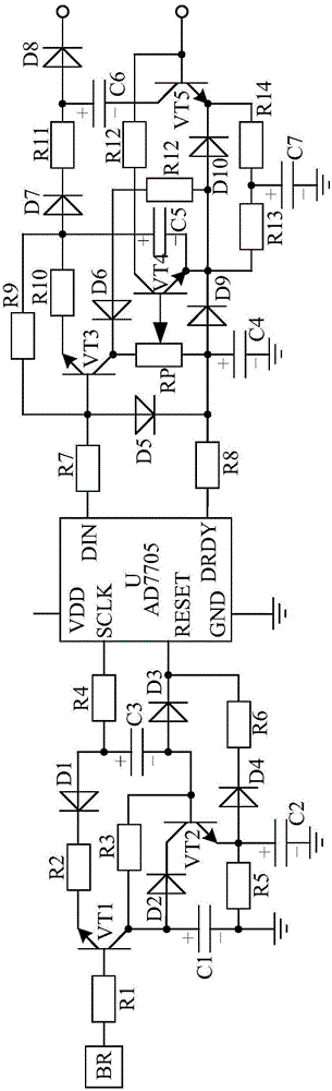
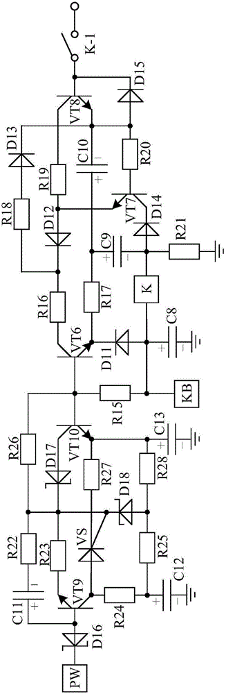
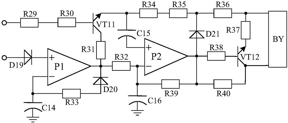
[0026] like Figure 1~3 As shown, the filtering and shaping general-purpose automatic clamping system of the present invention is mainly composed of a control chip U, a pressure sensor BR, a power source BY, a low-voltage rectifying circuit, a signal trigger circuit, a signal conversion circuit, a clamping control circuit and a filtering and shaping circuit. composition. The power source BY of the present invention is a motor, an air cylinder or a hydraulic cylinder, and the control chip U is an AD7705 integrated chip. The input terminal of the low-voltage rectification circuit is connected with the power supply PW, and the power supply PW of the present invention is a 220V low-voltage commercial power supply. The input end of the signal trigger circuit is connected to the output end of the low-voltage rectification circuit, and its output end is connected to the VDD pin of the control chip U. The input end of the signal conversion circuit is connected to the pressure sensor...


PUM


Abstract

The invention discloses a signal-triggered startup low voltage rectifying and filtering type drive system for automatic clamping. The drive system is characterized by mainly consisting of a control chip U, a pressure sensor BR, a power source BY, a low voltage rectifying circuit, a signal triggering circuit, a filtering and shaping circuit, a clamping control circuit and a signal conversion circuit, wherein an input end of the low voltage rectifying circuit is connected with a power source PW, an input end of the signal triggering circuit is connected with an output end of the low voltage rectifying circuit, an output end of the signal triggering circuit is connected with a VDD pin of the control chip U, an output end of the filtering and shaping circuit is connected with the power source BY, an input end of the clamping control circuit is connected with a DIN pin and a DRDY pin of the control chip U, an output end of the clamping control circuit is connected with an input end of the filtering and shaping circuit, an input end of the signal conversion circuit is connected with the pressure sensor BR via an electric resistor R1, and an output end of the signal conversion circuit is connected with an SCLK pin and an RESET pin of the control chip U. The drive system is simile in structure, low in cost and strong in generality. The drive system is convenient to use, applicable to all kinds of clamping objects and suitable for popularization and application.

Description

technical field [0001] The invention relates to a clamping system, in particular to a low-voltage rectification and filtering drive system triggered by a signal for automatic clamping. Background technique [0002] In the production and processing industry, it is often necessary to clamp tools or workpieces, that is, to clamp after completing the installation of tools or workpieces. At present, manual clamping or automatic control clamping is usually used for clamping. The efficiency of manual clamping is low. When the clamping object is large in size or heavy in weight, it often requires the cooperation of multiple people to complete it, and the clamping accuracy is completely determined by the operator based on work experience. The efficiency and precision of the automatic control clamping method are relatively high, but the structure of the automatic control clamping system currently used is relatively complicated and the cost is relatively high. The system used for auto...

Claims


Application Information

Patent Timeline
Patent Type & Authority Applications(China)
IPC IPC(8): H02M7/217H02M7/155
CPCH02M7/217H02M7/1557
Inventor 韩群芳
Owner CHENGDU CLAY STAR TECH CO LTD
Why Eureka
Try Eureka