Wideband bias circuits and methods

A bias circuit and circuit technology, which can be applied to amplifiers with semiconductor devices/discharge tubes, electrical components, and parts of amplifying devices, etc., and can solve problems such as affecting circuit operation.

Active Publication Date: 2016-07-13
QUALCOMM INC
View PDF4 Cites 9 Cited by
  • Summary
  • Abstract
  • Description
  • Claims
  • Application Information

AI Technical Summary

Problems solved by technology

However, in applications where the supply voltage changes, resistance and capacitance can affect the operation of the circuit

Method used


Image

  • Wideband bias circuits and methods
  • Wideband bias circuits and methods
  • Wideband bias circuits and methods

Examples


Embodiment Construction

[0032] This disclosure is applicable to broadband bias circuits. In the following description, for purposes of explanation, several examples and specific details are set forth in order to provide a thorough understanding of the present disclosure. However, it should be apparent to those skilled in the art that the present disclosure as expressed in the claims may include some or all of the features of these examples alone, or in combination with other features described below, and may further include Modifications and equivalents of features and concepts.

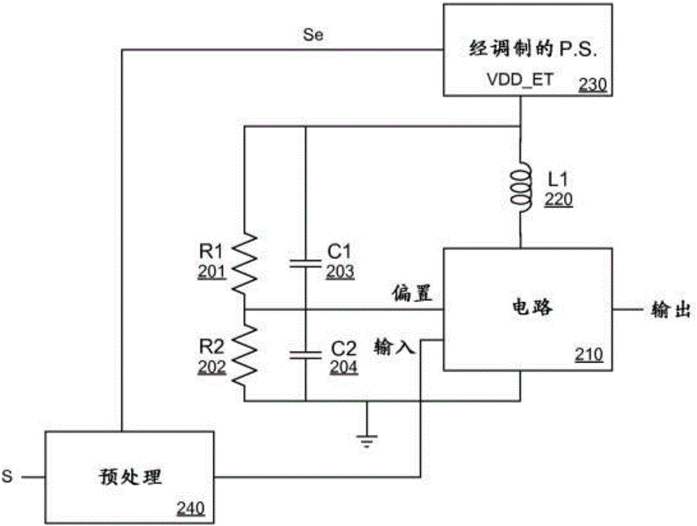
[0033]Some embodiments of the present disclosure may be applicable to envelope tracking applications. In envelope tracking applications, the supply voltage Vdd can be varied with time to reduce the power consumption of the circuit. The time-varying power supply voltage can correspond to the input signal, so that the input signal can be processed using less power. One exemplary system that uses envelope tracking (ET) is a...


PUM


Abstract

The present disclosure includes circuits and methods for wideband biasing. In one embodiment, an amplifier includes a cascode transistor (311) between an input and an output of the amplifier. The cascode transistor (311) receives a bias from a bias circuit comprising a resistor (301) between the power supply (VDD ET) and a first node, a resistor (302) between the first node and a reference voltage, and a capacitor (303) between the power supply (VDD ET) and the first node. The power supply (VDD ET) may be a modulated power supply, which is coupled through the bias circuit to a capacitance (303) at the control terminal of the cascode transistor (311). An inductor (310) is configured between a terminal of the cascode transistor (311) and the power supply (VDD ET). The inductor (310) may isolate the output from the modulated supply signal (VDD ET).

Description

[0001] Cross References to Related Applications [0002] This disclosure claims priority to US Application No. 14 / 172,150, filed February 4, 2014, the contents of which are hereby incorporated by reference in their entirety for all purposes. This disclosure claims priority to US Provisional Application No. 61 / 876,347, filed September 11, 2013, the contents of which are hereby incorporated by reference in their entirety for all purposes. technical field [0003] The present disclosure relates to electronic circuits and methods, and more particularly to broadband biasing circuits and methods. Background technique [0004] Stacked CMOS transistors are sometimes coupled in order to split the voltage swing across multiple devices for reliability purposes. figure 1 A typical amplifier stage is shown. The input signal is applied to the gate of the bottom MOS device 101 (eg, in a common source (CS) configuration). The top cascode device 102 (in a common gate (CG) configuration)...

Claims


Application Information

Patent Timeline
Patent Type & Authority Applications(China)
IPC IPC(8): H03F1/02H03F1/22H03F3/193H03F1/48
CPCH03F1/0266H03F1/223H03F1/483H03F2200/18H03F2200/36H03F3/193H03F1/0222H03F2200/21H03F2201/3215H03F1/0244H03F1/0211H03F3/245
Inventor J·卡巴尼拉斯C·D·普雷斯蒂
Owner QUALCOMM INC
Why Eureka
Try Eureka