Heavy boring cutter

A rough boring tool and tool holder technology, which is applied to rough boring tools. It can solve the problems such as the inability to adjust the processing range, the small processing space, and the reduction of the surface processing accuracy of the workpiece, and achieve the effect of good market prospects and economic value, good surface processing accuracy, and saving processing time.

Inactive Publication Date: 2016-07-20
NINGBO DANDERUI PRECISION MACHINERY TECH CO LTD
View PDF6 Cites 5 Cited by
  • Summary
  • Abstract
  • Description
  • Claims
  • Application Information

AI Technical Summary

Problems solved by technology

In the traditional rough boring, some of the tool holders and the cutter body are screwed together, and some of the tool holders are integrally formed with the cutter body. Most of the tool holders are integral, and multiple blades are fixed on the tool holder. , the entire tool holder needs to be replaced. First, the replacement cost is high. Second, the overall structure is more cumbersome and cannot be replaced quickly. Third, the tool holder and the blade are fixed, and the processing range cannot be adjusted, which is difficult to meet actual production needs.
In addition, the traditional rough boring tool has a small machining space between the insert and the workpiece, and the debris generated during cutting accumulates instantaneously. Injury, resulting in greatly reduced surface machining accuracy of the workpiece, resulting in increased production costs, affecting economic benefits

Method used


Image

  • Heavy boring cutter
  • Heavy boring cutter
  • Heavy boring cutter

Examples


Embodiment Construction

[0017] The present invention will be further described in detail below in conjunction with the accompanying drawings and specific embodiments.

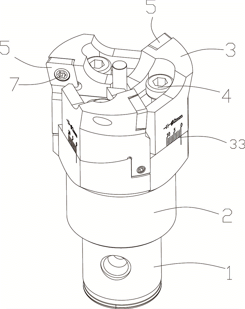
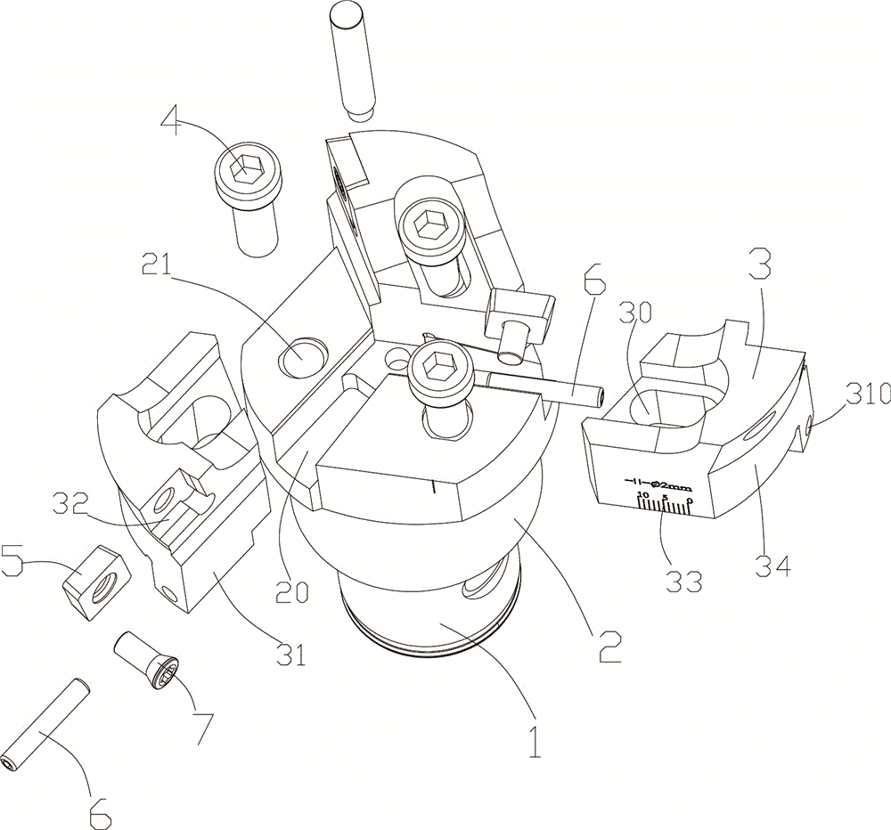
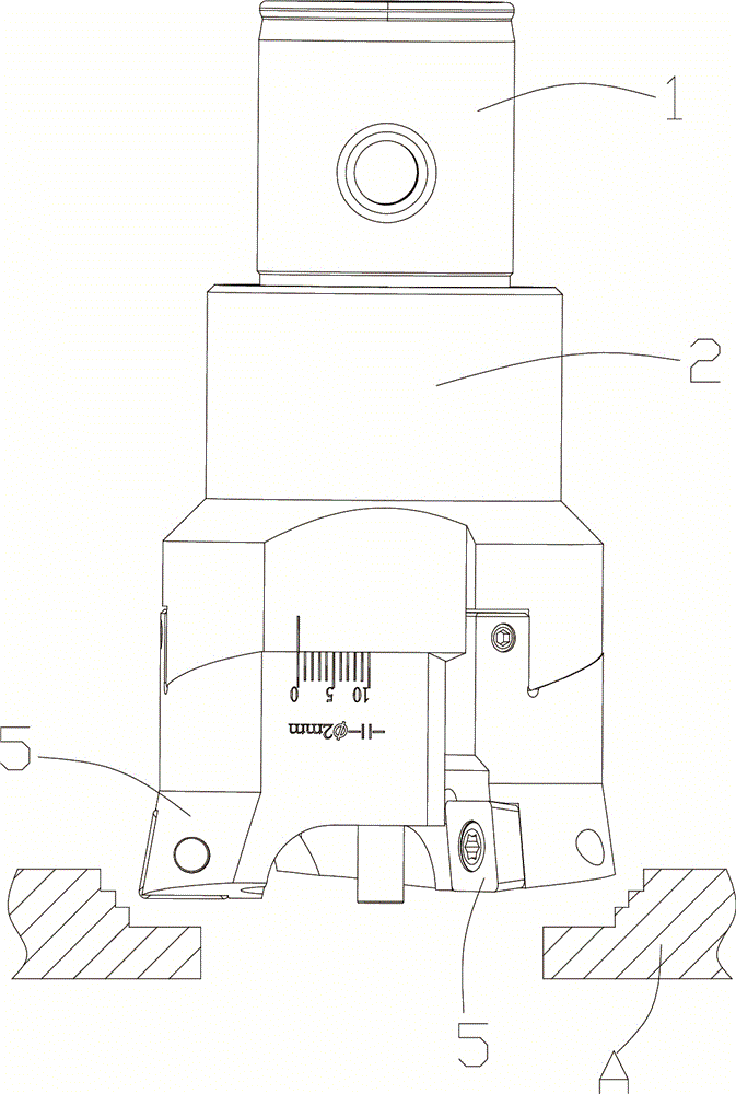
[0018] see Figure 1 to Figure 3 Shown, a specific embodiment of the rough boring tool of the present invention. A rough boring tool, including a round handle 1 inserted into a machine tool and a tool bar 2, several chute 20 is arranged on the tool bar 2, and a blade seat 3 is slidably arranged on the chute 20, in the A waist hole 30 is provided on the blade seat 3, and a threaded hole 21 corresponding to the position of the waist hole 30 is provided on the knife rod 2, and a fastener 4 is screwed into the threaded hole through the waist hole 30 21. Fix the blade seat 3 on the cutter bar 2, and the blade seat 3 is provided with a blade 5.

[0019] In the above technical solution, a boss 31 matching with the chute 20 is provided on the blade holder 3, a through hole 310 is arranged on the boss 31, and a countersunk screw 6 passes thr...


PUM


Abstract

The invention discloses a heavy boring cutter and belongs to the field of machining cutters. The heavy boring cutter comprises a round handle inserted into a machine tool and a cutter bar; the cutter bar is provided with a plurality of sliding grooves, blade bases are arranged on the sliding grooves in a sliding mode and are provided with kidney-shaped holes, the cutter bar is provided with threaded holes corresponding to the kidney-shaped holes in position, fasteners penetrate through the kidney-shaped holes and are screwed into the threaded holes respectively for fixing the blade bases to the cutter bar, and blades are arranged on the blade bases. Compared with the prior art, when the heavy boring cutter is used for milling work-pieces, the blade bases on the heavy boring cutter can slide in the sliding grooves, the distance between the blade bases and the center of the cutter bar can be adjusted by adjusting a countersink screw according to the producing and machining requirements, then the diameters of bored holes can be adjusted, a higher feed rate can be realized for users, the blades are saved, the machining time is greatly shortened, the machining cost is lowered, the market prospect is wide, and the economic value is high.

Description

technical field [0001] The invention belongs to the field of machining tools, in particular to a rough boring tool. Background technique [0002] A milling cutter is a rotating tool with one or more teeth for milling. When working, each knife tooth cuts off the allowance of the workpiece intermittently in turn. Milling cutters are mainly used to process planes, steps, grooves, forming surfaces and cut off workpieces on milling machines. They are divided into rough boring cutters and fine boring cutters according to the machining accuracy. [0003] The rough boring tool is a kind of cutting tool, and the rough boring tool is mainly used for preliminary cutting of the workpiece to be processed. In the traditional rough boring, some of the tool holders and the cutter body are screwed together, and some of the tool holders are integrally formed with the cutter body. Most of the tool holders are integral, and multiple blades are fixed on the tool holder. , the entire tool hold...

Claims


Application Information

Patent Timeline
Patent Type & Authority Applications(China)
IPC IPC(8): B23B27/16B23B29/034
CPCB23B27/1644B23B29/03407B23B2200/0428B23B2205/04
Inventor 张海涛陈达炳
Owner NINGBO DANDERUI PRECISION MACHINERY TECH CO LTD
Why Eureka
Try Eureka