
Fine-tuning cradle structure

A technology of cradle and adjusting bracket, which is applied in textiles and papermaking, drafting equipment, spinning machines, etc. It can solve the problems of pressure and angle changes of cradle, influence on yarn consistency, low assembly efficiency, etc., and achieve stable cradle Reduce the pressure value of the rack, reduce labor intensity, and solve the effect of automatic pressure relief

Active Publication Date: 2018-05-15
常州市同和纺织机械制造有限公司
View PDF6 Cites 0 Cited by
  • Summary
  • Abstract
  • Description
  • Claims
  • Application Information

AI Technical Summary

Problems solved by technology

However, during the operation process, the locking screw is set on the rear side of the locking plate. When fixing the position of the cradle, it needs to be operated from the rear, and the V-shaped groove on the pole shaft is located at the lower part, so the pressure adjusting screw also needs to be operated from the rear. The lower part is operated upwards, which is time-consuming and labor-intensive during the installation and debugging process and pressure adjustment, resulting in low assembly efficiency
Furthermore, in the spinning work, it is necessary to open or press the handle frequently, and the torque during the handle operation will act on the pole shaft through the locking piece. Since the pole shaft is fixed on the machine base, the locking piece on the The torque will also act on the locking screw and the pressure adjusting screw, which not only easily causes damage to the surface of the strut shaft, but also causes the loosening of the pressure adjusting screw and the locking screw, which in turn causes changes in the pressure and angle of the cradle, resulting in Automatic pressure relief phenomenon, affecting the consistency of the yarn
In order to improve the assembly and installation efficiency of the cradle, the eccentric wheel is currently used to lock the pole shaft. Although the eccentric wheel can quickly install the cradle on the pole shaft, during the spinning process, the torque of the operating handle also acts on the On the cam, if the cam cannot be locked, it will also cause automatic pressure relief, which will also affect the consistency of spinning

Method used


Image

  • Fine-tuning cradle structure
  • Fine-tuning cradle structure
  • Fine-tuning cradle structure

Examples


Embodiment Construction

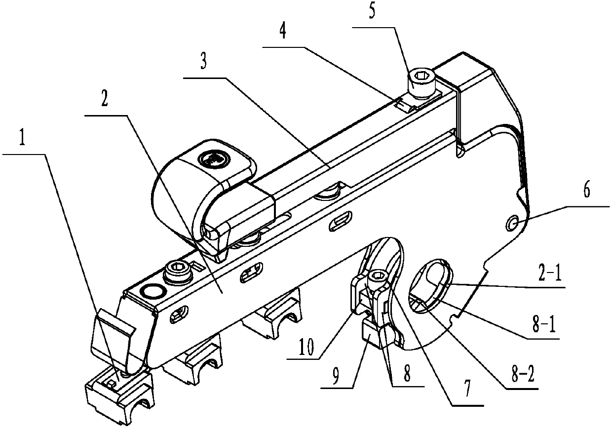
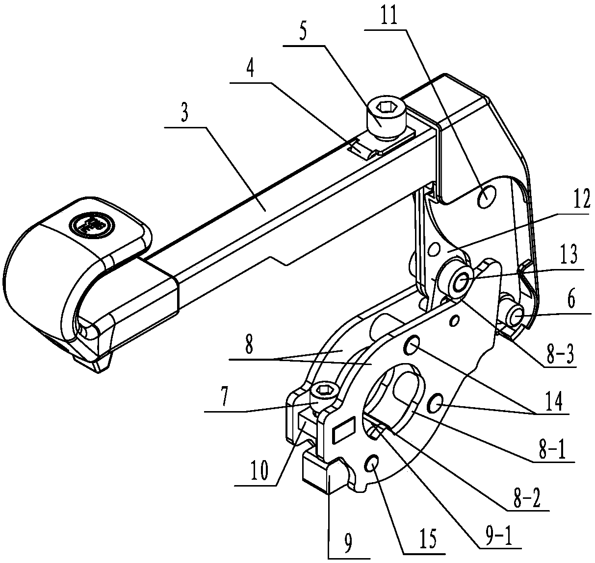
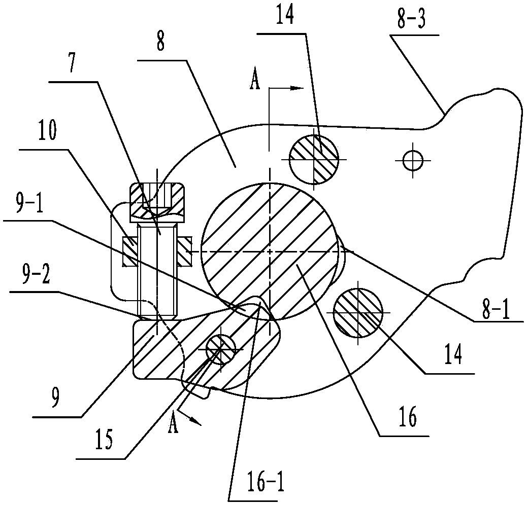
[0023] See Figure 1~5 As shown, the fine-tuning cradle structure of the present invention includes a handle 3, a cradle body 2 hinged on the handle 3, at least three pressurizing mechanisms 1 arranged on the cradle body 2, and a rod shaft for The upper locking mechanism on 16, the cradle body 2 and the two locking plates 8 of the locking mechanism are provided with the first pole hole 2-1 and the second pole hole 8-1 through which the pole shaft 16 passes, The first pole hole 2-1 of the cradle body 2 and the second pole hole 8-1 on the two locking pieces 8 are connected to the pole shaft 16 through the pole shaft 16, and the pole shaft 16 is then Installed on the machine base, each pressing mechanism 1 of the present invention adopts the existing structure, and the holding seat on each pressing mechanism 1 is then connected to the corresponding top roller, so that the top roller and each bottom roller correspond to form a drafting zone, and the fiber Do the drafting.

[002...


PUM


Abstract

The invention relates to a fine adjustment type cradle structure. The fine adjustment type cradle structure comprises a handle, a cradle body, a pressing mechanism and a locking mechanism, wherein a nut is fixed to the front parts of two locking sheets of the locking mechanism; a locking screw is mounted on the nut; a positioning block is mounted at the front lower part between the two locking sheets via a low connecting pin; the locking screw is jacked at the front part of the positioning block; a lug at the rear part of the positioning block is used for locking a V-shaped groove; a pressure fine adjustment mechanism is also arranged at the rear part of the handle; an adjusting bracket of the pressure fine adjustment mechanism comprises an adjusting seat arranged at the rear upper part of the handle and a connection plate arranged in a handle connector; the locking nut is fixed on the handle; a pressure adjusting screw penetrates through a mounting hole of a positioning spring, is screwed with the locking nut and is jacked at the front part of the adjusting seat; the rear part of the connection plate is articulated with the handle connector; a roller sleeve pin is mounted at the front lower part of the connection plate. The fine adjustment type cradle structure is convenient and rapid to mount and adjust, is integrated with functions of locking and adjusting the pressure, and is capable of reliably adjusting the pressure; the problem of automatic pressure release is solved.

Description

technical field [0001] The invention relates to a fine-tuning cradle structure, belonging to the technical field of spinning machine cradles. Background technique [0002] The cradle used for the spinning frame textile machine mainly includes a cradle body, a handle, three pressure mechanisms installed on the cradle body from front to back, and a locking mechanism for connecting to the pole shaft, three for each The spring seat of the pressurizing mechanism is installed with its own corresponding holding seat, and the top rollers are correspondingly installed in the holding seat. The three top rollers and the corresponding three bottom rollers form a drafting area. The thick fiber strips in between are drawn and twisted to form thin fiber strips. Since the cradle is installed on the pole shaft connected to the machine base, there are pole holes on the two locking pieces and the cradle body, and a pressure regulating nut, A lock nut is fixed on the rear side, and the adjust...

Claims


Application Information

Patent Timeline
Patent Type & Authority Patents(China)
IPC IPC(8): D01H5/50
CPCD01H5/50
Inventor 唐国新刘金全郭桂松周豪严绪东王涛桑敏敏
Owner 常州市同和纺织机械制造有限公司
Learn More