Reducing reamer

A technology of a reamer and a body, which is applied in the special field of horizontal directional drilling method, can solve the problems of delaying human and material resources, wasting time, energy, material resources, financial resources, reverse reaming, etc. The effect of working efficiency, expanding the scope of application and reducing the risk of sticking

Active Publication Date: 2016-07-20
河北华元科工股份有限公司
View PDF7 Cites 3 Cited by
  • Summary
  • Abstract
  • Description
  • Claims
  • Application Information

AI Technical Summary

Problems solved by technology

[0004] However, in the actual crossing process of horizontal directional drilling, complex strata such as rocks are often encountered, and even the construction site is limited. During construction, the reverse reaming cannot be carried out according to the conventional process, and the hole can only be reamed at the entry point. Pushing and reaming, these have certain requirements on the applicability, life and working efficiency of the reamer
If the reamer gets stuck during the retraction process and the drill pipe cannot be taken out, the entire line will be scrapped, which will not only waste the time, energy, material and financial resources invested, but also need to organize experts to re-discuss and verify the new construction lines, resulting in the delay of the entire project and a serious waste of human and material resources

Method used


Image

  • Reducing reamer
  • Reducing reamer

Examples


Embodiment Construction

[0024] Below in conjunction with accompanying drawing and embodiment the present invention is described in further detail:

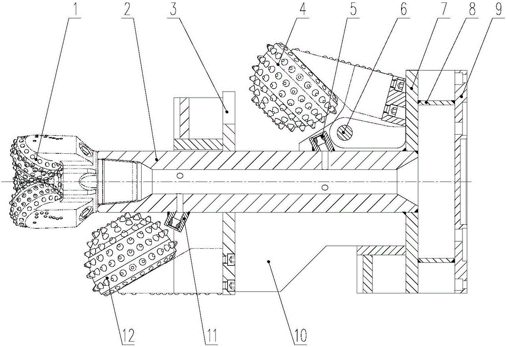
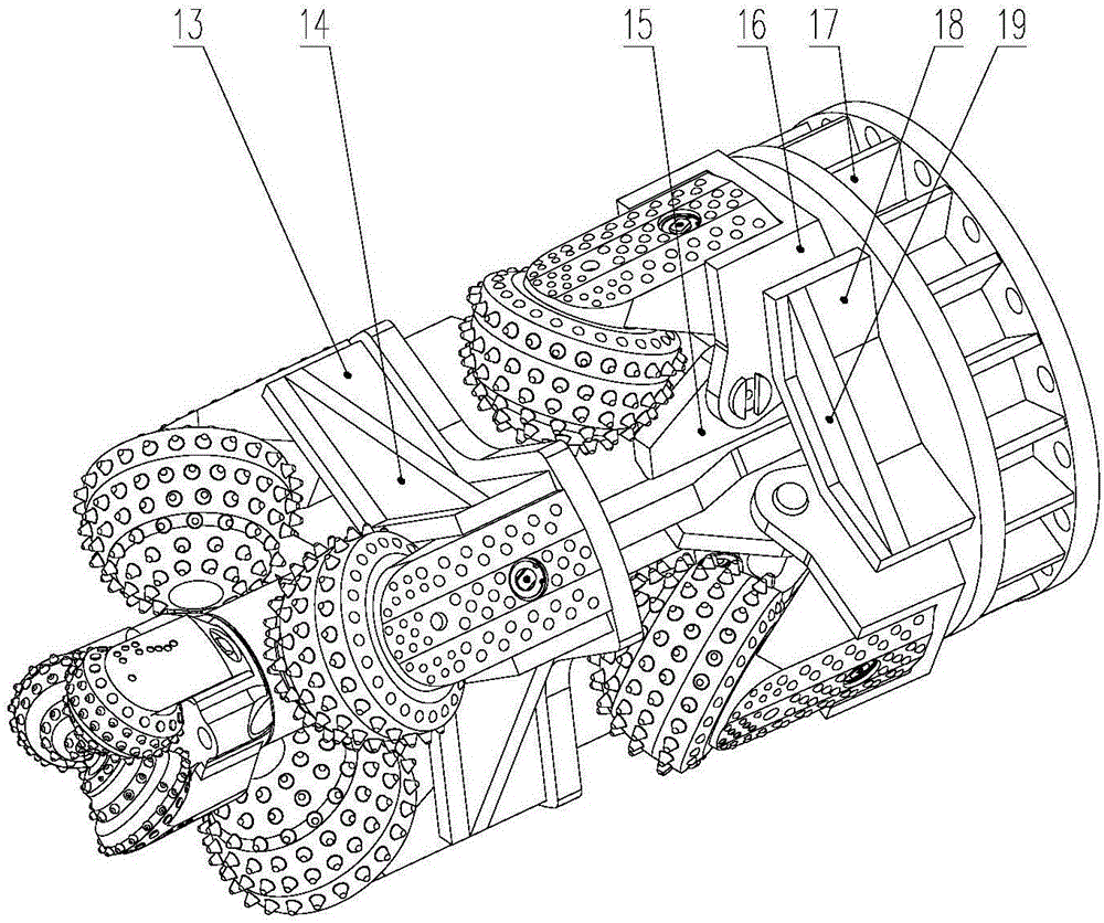
[0025] A variable diameter reamer, such as figure 1 and figure 2 As shown, the reamer body 2, the tri-cone bit 1, the fixed cone 12, the reversing cone 4 and the connection plate 9 are included. The front end of the reamer body 2 is the advancing direction of reaming, and the rear end is connected to the drilling rig, the pipe jacking machine or the power mechanism of the reamer through the connection plate 9 . The reamer body 2 is respectively connected with the three-cone bit 1, the fixed cone 12, the reversing cone 4 and the connecting plate 9 from front to back.

[0026] The head of the three-cone bit 1 is a structure in which three cones are fixedly connected, and the tail is a threaded rod with a tapered thread. The front end of the reamer body 2 is correspondingly provided with an internal thread taper hole. The reamer body 2 is fixedly connec...


PUM


Abstract

The invention discloses a reducing reamer which comprises a reamer body, a tricone bit, a fixed cone and a turnover cone, wherein the tricone bit is connected with the front end of the reamer body; the fixed cone is arranged at the middle part of the reamer body through a connecting seat plate; the turnover cone is arranged at the tail part of the reamer body through a seat plate; the tail end of the turnover cone is fixedly connected with a turning plate; the turning plate extends to form downward wing plates corresponding to the two sides of the turnover cone; the two wing plates are separately in hinge joint with fixing plates arranged on the two sides of the turnover cone in advance; a positioning plate is arranged on the seat plate corresponding to the turning plate of the turnover cone; and a connecting disc is arranged on one side of the seat plate corresponding to the tail part of the reamer body. In the invention, during pipeline crossing with complex formation and limited construction site, the turnover cone in reaming drilling rotates around the hinge pin of the turning plate under the effect of rock-soil resistance in the advancing direction, and the cutting diameter is increased; and for retreating, the turnover cone rotates to the initial position under the frictional resistance of the hole wall rock and soil, the diameter of the reducing reamer is reduced, and thus the risk of tool sticking in the retreating process is lowered.

Description

technical field [0001] The invention relates to the special technical field of horizontal directional drilling crossing, in particular to a variable-diameter reamer used for horizontal directional drilling crossing pipe jacking and hole reaming. Background technique [0002] Horizontal directional drilling crossing is a non-excavation pipeline installation and construction method that uses horizontal directional drilling rigs to conduct pilot holes and reaming operations according to the designed trajectory, and drags back to cross the pipeline through obstacles. It is used for oil, natural gas, tap water, sewage, gas , electricity, telecommunications and other pipeline laying or renewal. [0003] What is widely used at present is the cone type rock reamer, which includes a circular tubular main body, and a fixing plate is welded perpendicular to the main body of the reamer. Along the axial direction of the reamer, one of the fixing plates Four first cones are fixed on the ...

Claims


Application Information

Patent Timeline
Patent Type & Authority Applications(China)
IPC IPC(8): E21B10/26E21B10/28E21B10/34E21B10/60
CPCE21B10/26E21B10/28E21B10/34E21B10/60
Inventor 史占华
Owner 河北华元科工股份有限公司
Why Eureka
Try Eureka