Noise elimination gear

A technology of gears and gear bodies, applied in the directions of gear lubrication/cooling, belts/chains/gears, components with teeth, etc. Novel, reasonable design, noise reduction effect

Inactive Publication Date: 2016-07-20
李志聪
View PDF1 Cites 4 Cited by
  • Summary
  • Abstract
  • Description
  • Claims
  • Application Information

AI Technical Summary

Problems solved by technology

[0002] Since the second industrial revolution, the application of machinery has nearly occupied the entire manufacturing industry. Gears are an important part of the operation between various parts of machinery, but the noise generated by the gears during operation is relatively large. In the gear system, according to The mechanism is different, and the noise can be divided into two types: acceleration noise and self-sounding noise. On the one hand, when the gear teeth are meshing, the gear will generate a large acceleration due to the impact and cause the surrounding medium to be disturbed. The sound radiation produced is called the acceleration noise of the gear. On the other hand, under the action of the dynamic meshing force of the gear, the various parts of the system will vibrate. On the other hand, there are also many improvements. For example, in the Chinese patent application number: 201420227600.7, a patent is disclosed that a clamping block and a pressing block are arranged on both sides of the teeth, and the middle of the clamping block and the pressing block is connected by an elastic rod. Reduce the noise generated by the contact between teeth and teeth during the operation of the two gears, but the installation of the pressing block and the card will increase the cost and increase the complexity of producing the gear. Will wear out soon

Method used


Image

  • Noise elimination gear
  • Noise elimination gear

Examples


Embodiment Construction

[0013] In order to make the object, technical solution and advantages of the present invention clearer, the present invention will be further described in detail below in conjunction with the accompanying drawings and embodiments. It should be understood that the specific embodiments described here are only used to explain the present invention, not to limit the present invention.

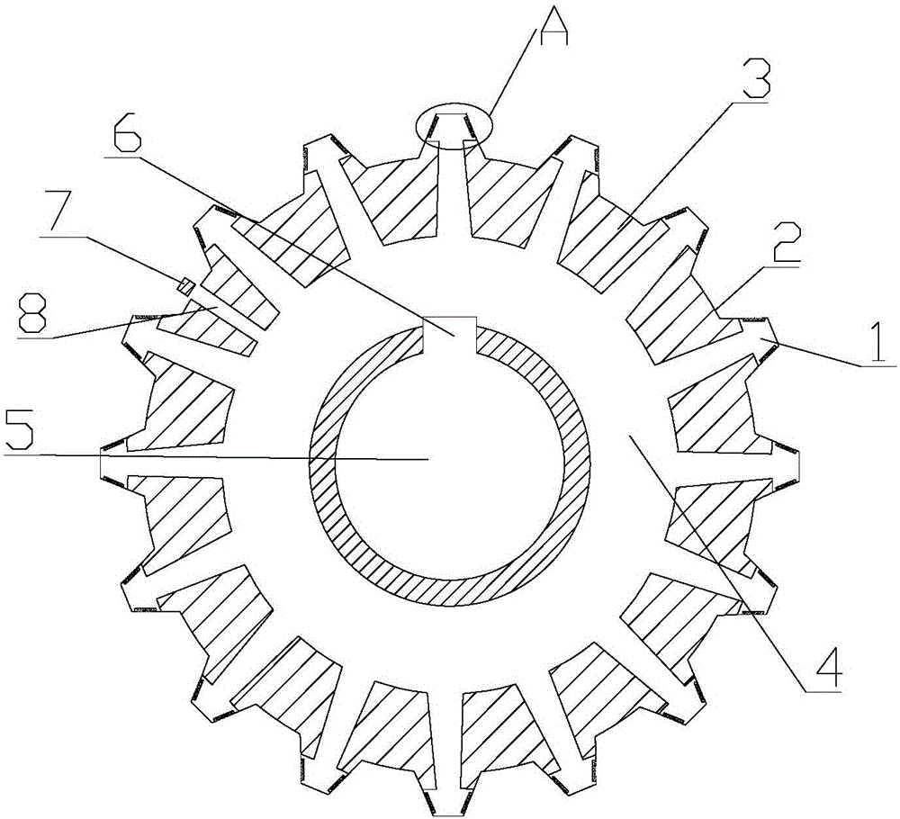
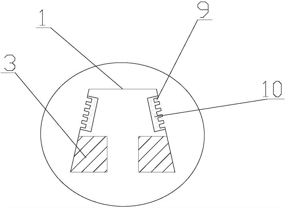
[0014] like figure 1 and figure 2 As shown, a noise reduction gear provided in this embodiment includes a gear body 3, teeth 1 are arranged on the outer contour of the gear body 3, and tooth grooves 2 are arranged between adjacent teeth 1. The gear A shaft hole 5 is opened at the center of the body 3, and a keyway 6 is provided on the inner wall of the shaft hole 5 and along the radial direction of the gear body 3. The surface of the gear body is covered with a nickel-plated layer, which can reduce the appearance of the gear during long-term use. Rust situation, thus prolonging its service life....


PUM


Abstract

The invention discloses a noise elimination gear which comprises a gear body, and further comprises elastic gaskets, wherein gear teeth are arranged on the outer profile of the gear body; tooth grooves are formed between the adjacent gear teeth; a shaft hole is formed in the center of the gear body; a keyway is formed in the inner wall of the shaft hole in the radial direction of the gear body; straight holes with the same size as the elastic gaskets are formed in the outer surfaces of the two sides of the gear teeth; the elastic gaskets are embedded in the straight holes in the two sides of the gear teeth; and the outer surfaces of the elastic gaskets are flush with the outer surfaces of the gear teeth. According to the noise elimination gear, the structure is novel, the design is reasonable, and the elastic gaskets are arranged on the gear teeth, so that when two gears are mutually meshed for operation, and when the gear teeth are in contact with each other, the elastic gaskets can exert a reset function, the nose generated during gear transmission can be reduced, the vibration damping function is achieved, and the noise reduction effect is achieved.

Description

technical field [0001] The invention relates to the field of gears, in particular to a noise reduction gear. Background technique [0002] Since the second industrial revolution, the application of machinery has nearly occupied the entire manufacturing industry. Gears are an important part of the operation between various parts of machinery, but the noise generated by the gears during operation is relatively large. In the gear system, according to The mechanism is different, and the noise can be divided into two types: acceleration noise and self-sounding noise. On the one hand, when the gear teeth are meshing, the gear will generate a large acceleration due to the impact and cause the surrounding medium to be disturbed. The sound radiation produced is called the acceleration noise of the gear. On the other hand, under the action of the dynamic meshing force of the gear, the various parts of the system will vibrate. On the other hand, there are also many improvements. For e...

Claims


Application Information

Patent Timeline
Patent Type & Authority Applications(China)
IPC IPC(8): F16H55/17F16H55/16F16H55/06F16H57/04
CPCF16H55/17F16H55/06F16H55/16F16H57/0431
Inventor 李志聪
Owner 李志聪
Why Eureka
Try Eureka