Efficient dehaze waste heat recovery energy-saving emission reduction device

A waste heat recovery, energy-saving and emission-reduction technology, applied to heat exchange equipment, heat exchanger shells, heat exchanger types, etc., can solve problems such as increased maintenance costs, and achieve reduced emissions, improved efficiency, and high-efficiency heat exchange capabilities Effect

Inactive Publication Date: 2016-07-20
GUANGZHOU INST OF ENERGY CONVERSION - CHINESE ACAD OF SCI +1
View PDF7 Cites 4 Cited by
  • Summary
  • Abstract
  • Description
  • Claims
  • Application Information

AI Technical Summary

Problems solved by technology

This kind of regular maintenance not only caused the direct loss of a sharp increase in the maintenance cost of the enterprise, but also caused huge indirect losses due to the shutdown of the enterprise.

Method used


Image

  • Efficient dehaze waste heat recovery energy-saving emission reduction device
  • Efficient dehaze waste heat recovery energy-saving emission reduction device
  • Efficient dehaze waste heat recovery energy-saving emission reduction device

Examples


Embodiment

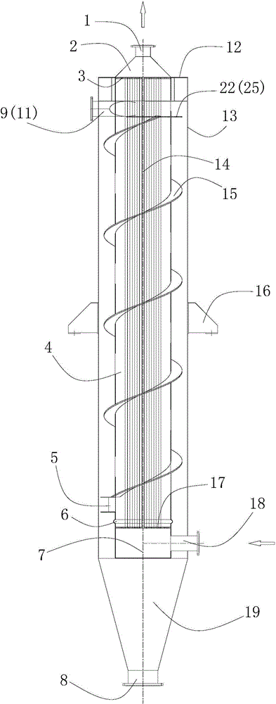
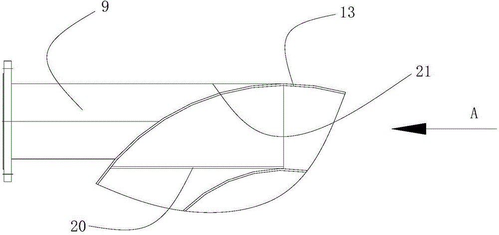
[0029] refer to figure 1 and figure 2, is a high-efficiency haze removal waste heat recovery energy-saving emission reduction device, installed vertically with the tail flue of the boiler, including SP heat exchange tube 14, upper tube plate 3, lower tube plate 17, inner cylinder 4, spiral plate 15 and outer Cylinder 13, SP heat exchange tube 14 is built in the inner cylinder 4, the upper end of SP heat exchange tube 14 is connected with the upper tube plate 3, and the lower end is connected with the lower tube plate 17; the upper end of the inner cylinder 4 is connected with the upper tube plate 3 The outer circle of the tube is connected, and the lower end is connected with the expansion joint 6 and then connected with the outer circle of the lower tube plate 17. The expansion joint 6 is located between the SP heat exchange tube 14 and the inner cylinder 4; the upper section of the inner cylinder 4 is provided with a flue gas The inlet nozzle 11, the flue gas inlet nozzle ...


PUM


Abstract

The invention discloses an efficient dehaze waste heat recovery energy-saving emission reduction device. The device comprises an SP heat exchange pipe, an upper tube plate, a lower tube plate, an inner barrel, a spiral plate and an outer barrel. The inner barrel is provided with a smoke inlet tube orifice and an inner barrel smoke outlet tube orifice. The lower tube plate is connected with a lower tube box provided with an air inlet tube orifice. The upper tube plate is connected with an upper tube box provided with an air outlet tube orifice. The spiral plate is spirally arranged on the outer wall of the inner barrel. The upper end of the inner barrel and the upper end of the outer barrel are connected through closure plates and reinforcing rib plates. The upper end of the outer barrel is provided with an outer barrel smoke outlet tube orifice, and the lower end of the outer barrel is connected with a dust hopper provided with a dust removing opening. The device has high heat exchange efficiency and can prolong the structure time of equipment, dust in smoke can be efficiently separated and removed, the emission amount of CO2, NOX and the like is effectively reduced, and resistance loss of the device is smaller than equipment of the same type under the same working condition. The size of the device is small, heat exchange, dust removal and dehazing are achieved, and the smoke temperature is lowered.

Description

technical field [0001] The invention relates to a high-efficiency heat exchange and dust removal device for waste heat recovery of flue gas in power station boilers, chemical heating furnaces, biomass boilers and industrial kilns, especially relates to a device for use in biomass boilers with large dust content in flue gas 1. A high-efficiency haze removal waste heat recovery energy-saving and emission-reduction device that works under the process conditions with high water content. Background technique [0002] With the continuous development of society, human beings are increasingly dependent on non-renewable energy sources, and environmental pollution is also becoming more and more serious. In order to alleviate the pressure of the environment and social development, biomass boilers are more and more favored by some enterprises. It not only solves the impact of the non-renewable energy crisis, but also eases the pressure on the environment. The fuel source of the biomass...

Claims


Application Information

Patent Timeline
Patent Type & Authority Applications(China)
IPC IPC(8): F23J15/02F28D7/00F28F9/22F28F9/26F28F19/01
Inventor 朱冬生莫逊沈大伟佘京鹏郭华芳李立鸿
Owner GUANGZHOU INST OF ENERGY CONVERSION - CHINESE ACAD OF SCI
Why Eureka
Try Eureka