
Device and method for measuring parameters of solution and liquid film on non-transmissive solid surface

A technology for parameter measurement and solid surface, applied in measurement devices, color/spectral property measurement, instruments, etc., can solve the problems of non-transmissive solids that cannot be directly applied, and cannot directly detect the reflected light of non-transmissive solids, etc., to achieve high-precision synchronization Measure and eliminate the effect of interference

Active Publication Date: 2019-01-01
UNIV OF SHANGHAI FOR SCI & TECH
View PDF6 Cites 0 Cited by
  • Summary
  • Abstract
  • Description
  • Claims
  • Application Information

AI Technical Summary

Problems solved by technology

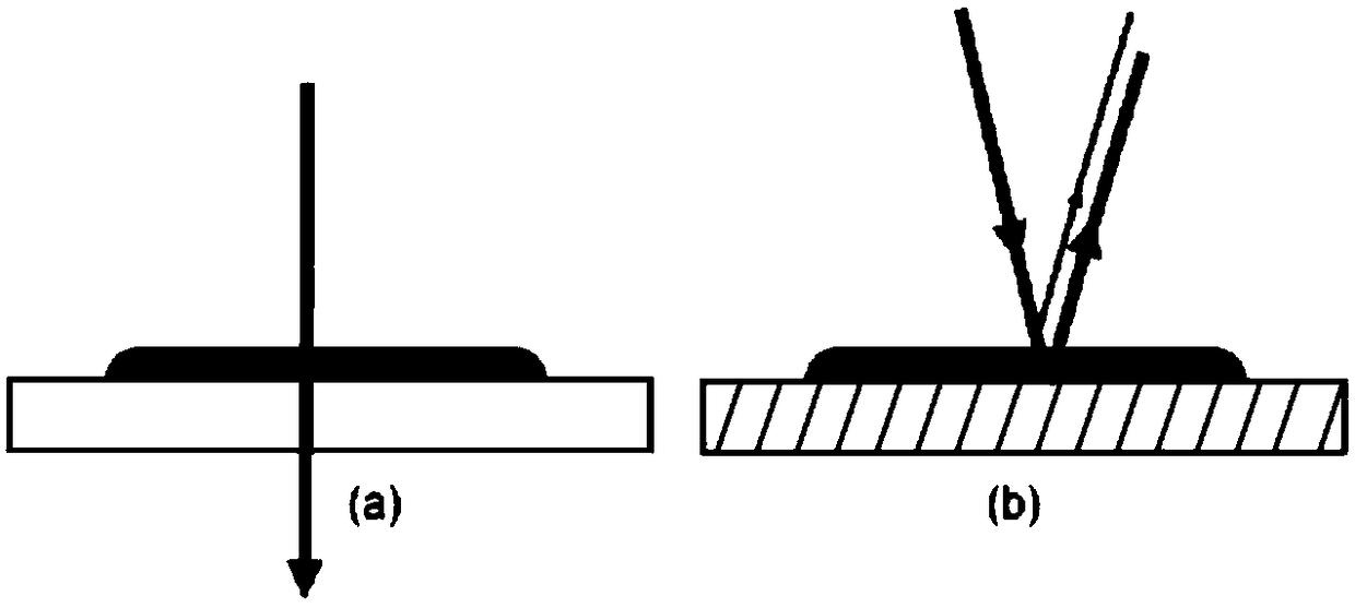
[0003] For a liquid film on the surface of a transmissive solid (such as a transparent quartz glass plate), such as figure 1 As shown in a, the laser directly passes through the liquid film and the transmission solid, and the parameters of the liquid film can be retrieved by placing a spectrum acquisition system under the transmission solid to obtain the information of the transmitted light intensity; but in actual industrial processes, the liquid film is usually in the non-transmission Formed on solid surfaces such as metals, such as figure 1 As shown in b, after the laser passes through the liquid film, it can no longer pass through the non-transmissive solid below to form transmitted light, but part of it is reflected on the surface of the liquid film to form the reflected light of the liquid film, and the other part passes through the liquid film of the solution in the non-transmissive Reflection occurs on the solid surface to form non-transmissive solid reflected light. Due to the interference of liquid film reflected light, it is impossible to directly detect the non-transmitted solid reflected light that has passed through the solution liquid film. Therefore, the liquid film parameter measurement device and method on the transmitted solid surface cannot be directly detected. Applied to non-transmissive solids

Method used


Image

  • Device and method for measuring parameters of solution and liquid film on non-transmissive solid surface
  • Device and method for measuring parameters of solution and liquid film on non-transmissive solid surface

Examples


Embodiment Construction

[0031] The specific embodiment of the present invention when the liquid film of the solution to be tested is a liquid film of urea solution and the parameters to be measured is thickness, concentration and temperature will be described below in conjunction with the accompanying drawings.

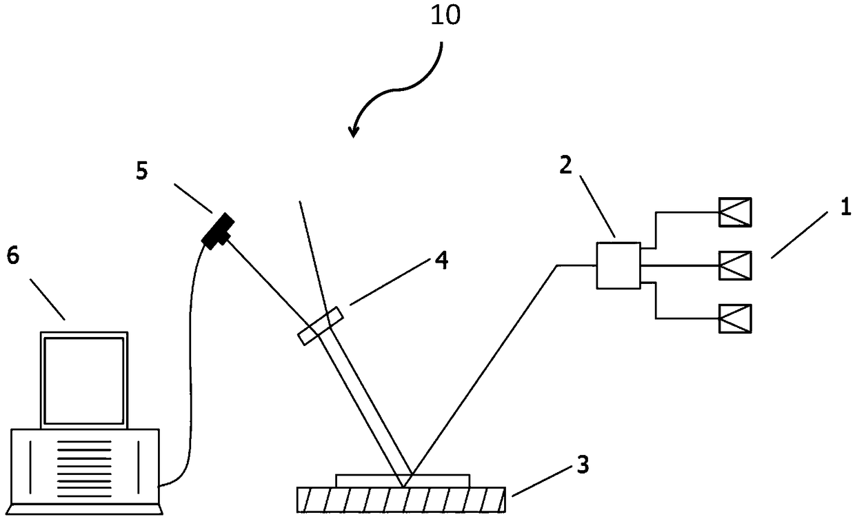
[0032] figure 2 The structural representation of the solution liquid film parameter measuring device on the non-transmissive solid surface provided by the present invention, such as figure 2 As shown, the device 10 includes a laser emitting unit 1 , a laser coupling unit 2 , a laser separation unit 4 , a spectrum acquisition system 5 and a computer 6 for measuring the parameters of the solution film on the surface of a non-transmissive solid 3 .

[0033] The laser emitting unit 1 is composed of three laser light sources with different wavenumbers; the laser coupling unit 2 is arranged on the optical path of the laser emitting unit 1, and is used to couple the three laser beams emitted by t...


PUM


Abstract

The invention provides a parameter measurement device and method for a solution film on a non-transparent surface, based on a multi-wavelength laser absorption spectroscopic technology, and is used for synchronously measuring various parameters of the solution film on a non-transparent surface. The device is characterized by comprising a laser emitting unit, a laser coupling unit, a laser separation unit, a spectrum acquisition system and a computer, wherein laser emitted by the laser emitting unit is coupled and projected to the solution film to be measured, and is reflected into reflected lights respectively on the non-transparent solid surface and the surface of the solution film to be measured; the two beams of reflected lights are separated through the laser separation unit; light signals of the reflected light on the non-transparent solid surface are gathered through the spectrum acquisition system, and are converted into electric signals to be transmitted to the computer for data processing; the parameters of the solution film can be determined through inversion.

Description

technical field [0001] The invention relates to a measuring device and a measuring method, in particular to a device and method for synchronously measuring multiple parameters of a solution liquid film on a non-transmissive solid surface, and the device and method are universal. Background technique [0002] In various industrial processes, the phenomenon that liquid droplets impinge on solid surfaces to form liquid films widely exists, such as the formation of urea aqueous solution liquid films on automobile exhaust pipes in selective catalytic reduction (SCR) systems, etc. High-precision quantitative analysis of multiple parameters such as liquid film thickness can not only better reveal the physical nature of the extremely complex process of liquid film formation, flow and evaporation, but also play a very important role in optimizing various industrial processes involved. significance. [0003] For a liquid film on the surface of a transmissive solid (such as a transpar...

Claims


Application Information

Patent Timeline
Patent Type & Authority Patents(China)
IPC IPC(8): G01N21/31G01N21/01
CPCG01N21/01G01N21/31
Inventor 杨荟楠彭莉吴威殷天明苏明旭蔡小舒
Owner UNIV OF SHANGHAI FOR SCI & TECH
Learn More