High-sensitivity light trap measuring device and measuring method thereof

A high-sensitivity, measurement device technology, applied in measurement devices, optical devices, velocity/acceleration/shock measurement, etc., can solve problems such as reduced sensitivity, reduced particle capture efficiency, and increased time for stable capture of microspheres

Active Publication Date: 2016-07-20
ZHEJIANG UNIV
View PDF5 Cites 17 Cited by
  • Summary
  • Abstract
  • Description
  • Claims
  • Application Information

AI Technical Summary

Problems solved by technology

[0006] Ordinary optical trap measurement devices, to achieve fast and stable capture of particles, need to use a more rigid optical trap, which will inevitably lead to small changes in the displacement of particles measured under the same acceleration, resulting ...

Method used


Image

  • High-sensitivity light trap measuring device and measuring method thereof
  • High-sensitivity light trap measuring device and measuring method thereof
  • High-sensitivity light trap measuring device and measuring method thereof

Examples


Embodiment Construction

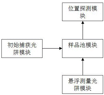
[0024] refer to figure 1 , a high-sensitivity optical trap measurement device, including four modules: a sample cell module, an initial capture optical trap module, a suspension measurement optical trap module, and a position detection module;

[0025] The sample cell module is provided with a sample cell and particles, and collimates the light path so that the balance point of the light trap formed by the initial captured light and the suspended light coincides. First, use the initial capture optical trap module to stably capture the particles at the balance point of the optical trap, then open the optical path of the suspended measurement optical trap, and remove the optical path of the initial capture optical trap at the same time, use the optical trap formed by the suspended light to re-stabilize the capture of particles, and use the position detection module To observe the capture effect of particles and detect the displacement signal of particles.

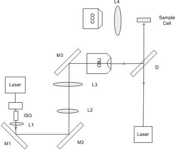
[0026] refer to fi...


PUM


Abstract

The invention discloses a high-sensitivity light trap measuring device and a measuring method thereof. The high-sensitivity light trap measuring device comprises a sample cell module, an initial capturing light trap module, a suspension measurement light trap module and a position detecting module. Firstly, particles are captured at a light trap balance point by means of initial capturing light and are quickly stabilized. Then suspension measuring light is started and simultaneously the initial capturing light is eliminated so that the particles are stabilized at the light trap balance point which is formed by the suspension measuring light. Then high-sensitivity measurement on a displacement signal and an acceleration signal is performed. According to the measuring method, on the condition of low damping in air or vacuum, capturing efficiency can be effectively improved and furthermore the particles are quickly stabilized, thereby preventing a defect of measurement application deterioration caused by long-time oscillation after capturing the particles by a low-rigidity light trap. The high-sensitivity light trap measuring device and the measuring method thereof have advantages of eliminating defects in a common light trap measuring device, realizing high-efficiency capture and quick stabilization of the particles, and furthermore obtaining high measurement sensitivity on the displacement signal and the acceleration signal.

Description

technical field [0001] The invention relates to an optical trap measuring device applied in the field of optical engineering, in particular to an optical trap measuring device and a measuring method thereof for precision measurement by using optical suspension. Background technique [0002] According to quantum theory, a light beam is a swarm of photons traveling at the speed of light that have both mass and momentum. When a photon is incident on the surface of the medium and undergoes refraction and reflection, the speed and direction of the photon change, resulting in a change in its momentum vector. From the law of conservation of momentum, it can be deduced that when a light beam enters a particle, the change in momentum of the photon is the change in momentum of the particle. Therefore, the effect of light beam on particles exists force, which is called optical radiation pressure. The light radiation pressure includes the scattering force along the beam propagation di...

Claims


Application Information

Patent Timeline
IPC IPC(8): G01P15/00G01B11/04
CPCG01B11/043G01P15/00
Inventor 胡慧珠葛晓佳李正刚舒晓武刘承
Owner ZHEJIANG UNIV
Why Eureka
Try Eureka