
Pixel driving structure, driving method and display device

A driving structure and pixel technology, applied in static indicators, instruments, etc., can solve the problems of large data line voltage swing and high power consumption of pixel driving structure, and achieve the effect of small pixel unit, lower power consumption, and lower cost.

Inactive Publication Date: 2016-07-20
KUSN INFOVISION OPTOELECTRONICS
View PDF5 Cites 16 Cited by
  • Summary
  • Abstract
  • Description
  • Claims
  • Application Information

AI Technical Summary

Problems solved by technology

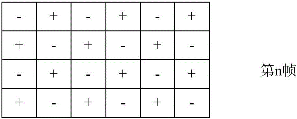
Wherein, if the reverse polarity of the sub-pixel in a sub-pixel unit is "+", it means that when the storage capacitor of the sub-pixel in the sub-pixel unit is charged through the data line, the final voltage is higher than the reference voltage; If the reverse polarity of the sub-pixel in a sub-pixel unit is "-", it means that when the storage capacitor of the sub-pixel in each sub-pixel unit is charged through the data line, the final voltage is lower than the reference voltage; however, When the pixel driving structure is driven by the dot inversion driving method, in each frame time, the voltage on each data line is sometimes higher than the reference voltage (voltage inversion polarity is "+") and sometimes lower It is higher than the reference voltage (the polarity of the voltage is reversed to "-"), which will cause a large voltage swing on the data line, which will cause a problem of large power consumption in the pixel driving structure.

Method used


Image

  • Pixel driving structure, driving method and display device
  • Pixel driving structure, driving method and display device
  • Pixel driving structure, driving method and display device

Examples


Embodiment Construction

[0036] Various embodiments of the invention will be described in more detail below with reference to the accompanying drawings. In the various drawings, the same elements are denoted by the same or similar reference numerals. For the sake of clarity, various parts in the drawings have not been drawn to scale.

[0037] The invention can be embodied in various forms, some examples of which are described below.

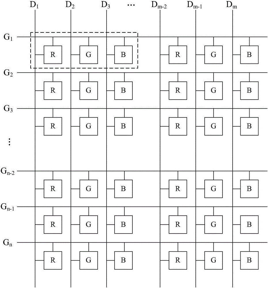
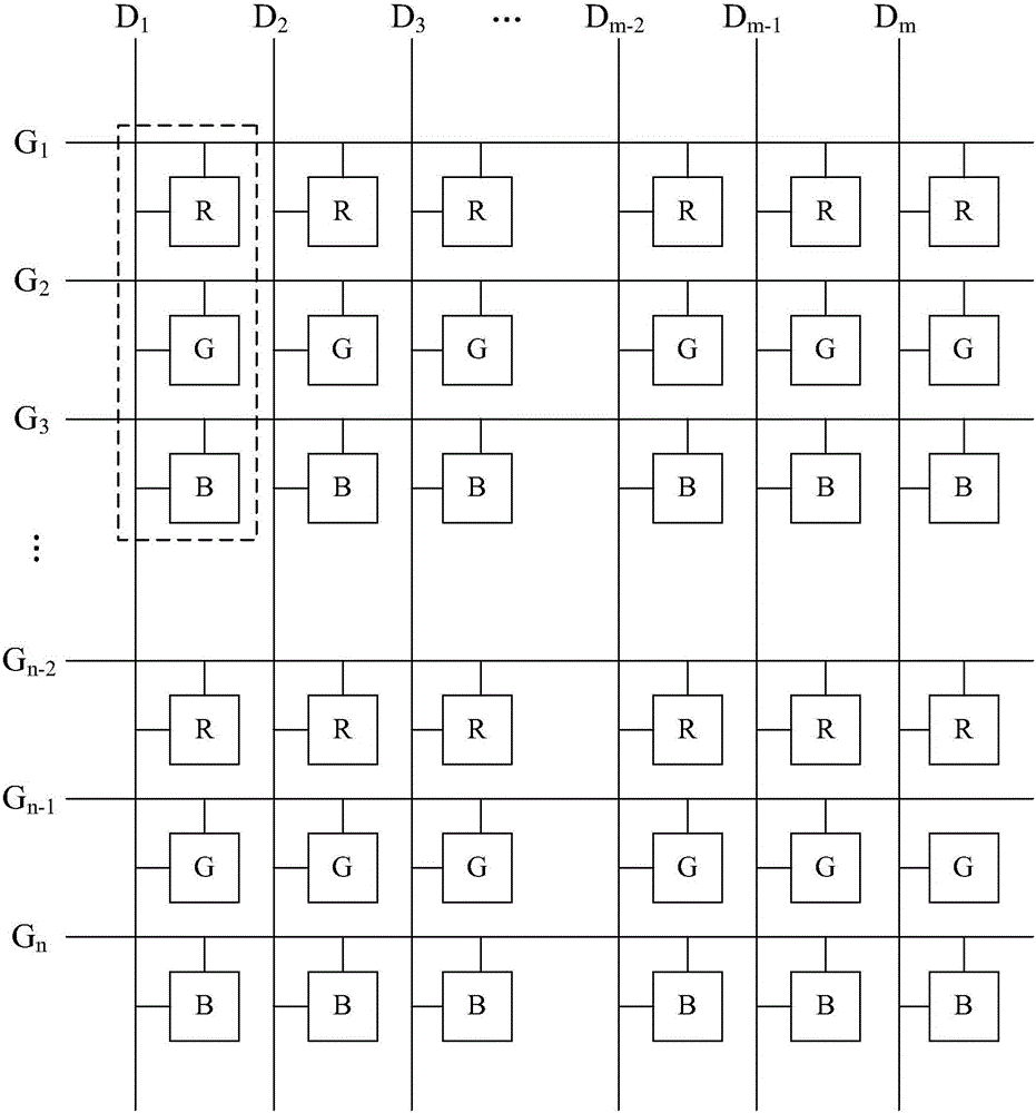
[0038] The embodiment of the present invention provides a pixel structure, which can be specified in Figure 4 The schematic structural diagram of the pixel driving structure shown, the pixel driving structure includes M data lines and N scanning lines, and the M data lines are vertically arranged in columns and parallel to each other (such as Figure 4 D shown 1 、D 2 、D 3 ,...,D M-1 、D M ), the N scanning lines are arranged horizontally and parallel to each other (such as Figure 5 ~ Figure 6 G shown 1 , G 2 , G 3 , G 4 , G 5 , G 6 ,...,G N-1 , G N ), sa...


PUM


Abstract

The invention discloses a pixel driving structure, which comprises multiple sub pixel electrodes, multiple data lines and multiple scanning lines, wherein the multiple sub pixel electrodes are arranged in an array; and the multiple data lines and the multiple scanning lines are arranged in a crossed mode. The pixel driving structure is characterized in that at least one data line is electrically connected with at least three sub pixel electrodes with the same data signal voltage polarity, and in a row direction or a column direction, the sub pixel electrodes connected with the same data line are connected with different scanning lines; and when a frame of image is displayed, the voltage polarity of the data signals applied to each data line remains unchanged, and the voltage polarities of data signals applied to adjacent two data lines are opposite. The pixel driving structure provided by the invention reduces the data line use amount, Z inversion can be realized, and low cost and low power consumption are realized.

Description

technical field [0001] The invention belongs to the technical field of liquid crystal display, and more specifically relates to a pixel driving structure, a driving method and a display device. Background technique [0002] Liquid crystal display (Liquid Crystal Display, LCD) has many advantages such as light and thin, energy-saving, non-radiation, etc., so it has gradually replaced the traditional cathode ray tube (CRT) display. Currently, liquid crystal displays are widely used in high-definition digital televisions, desktop computers, personal digital assistants (PDAs), notebook computers, mobile phones, digital cameras and other electronic devices. [0003] Such as figure 1 As shown, it is a schematic diagram of a pixel driving structure of a traditional TFT (Thin Film Transistor, Thin Film Field Effect Transistor) LCD in the prior art. The pixel driving structure includes M data lines (DataLine, also referred to as SourceLine), N scanning lines ( GateLine, which can a...

Claims


Application Information

Patent Timeline
IPC IPC(8): G09G3/36
CPCG09G3/3614G09G3/3677G09G3/3688
Inventor 杨发胜陈龙
Owner KUSN INFOVISION OPTOELECTRONICS
Learn More