
Novel cylindrical surface luneberg lens antenna capable of realizing circular polarization or bi-circular polarization

A Lumber lens antenna, double circular polarization technology, applied in the direction of antennas, electrical components, etc., can solve the problems of increasing the difficulty of antenna processing, reducing antenna efficiency, and complicating the antenna structure, so as to improve the reusability rate and simplify processing , to achieve the effect of lightweight

Active Publication Date: 2016-07-20
UNIV OF ELECTRONICS SCI & TECH OF CHINA
View PDF6 Cites 10 Cited by
  • Summary
  • Abstract
  • Description
  • Claims
  • Application Information

AI Technical Summary

Problems solved by technology

After loading the circularly polarized radome, it not only increases the difficulty of antenna processing, but also brings a series of problems such as complex antenna structure, increased loss, and reduced antenna efficiency.
[0005] In view of the phenomenon that the cylindrical Lunberg lens antennas involved in the published patents and papers are mostly linearly polarized, the present invention proposes a new type of circularly polarized or double circularly polarized cylindrical Lunberg lens based on a dielectric plate waveguide Antenna, the cylindrical Lunberg lens antenna can achieve circular polarization or dual circular polarization by using a linearly polarized feed

Method used


Image

  • Novel cylindrical surface luneberg lens antenna capable of realizing circular polarization or bi-circular polarization
  • Novel cylindrical surface luneberg lens antenna capable of realizing circular polarization or bi-circular polarization
  • Novel cylindrical surface luneberg lens antenna capable of realizing circular polarization or bi-circular polarization

Examples


Embodiment Construction

[0022] specific implementation plan

[0023] In order to make the purpose, technical solution and advantages of the present invention clearer, the present invention will be further described in detail below in conjunction with the implementation methods and accompanying drawings.

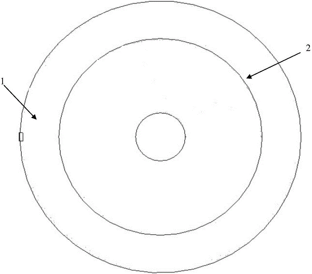
[0024] see figure 1 , figure 2 and image 3 , the novel circular polarization of the present invention and double circular polarization cylindrical Lunberg lens antenna comprise the linear polarization feed antenna 1 ( When realizing dual circular polarization, it should be replaced with a dual-linear polarization feed) and to meet the required refractive index and to make the horizontally polarized TEO wave and the vertically polarized TMO wave produce a 90° phase difference with a certain rotationally symmetrical cross-sectional shape Dielectric plate waveguide lens 2. According to the propagation characteristics of electromagnetic waves in the dielectric plate waveguide, the refractive index...


PUM


Abstract

The invention discloses a novel cylindrical surface luneberg lens antenna capable of realizing circular polarization or bi-circular polarization. The novel cylindrical surface luneberg lens antenna mainly comprises a linear polarization feed source antenna 1 which is attached to the circumferential surface of a cylindrical lens and of which the polarization direction is in a 45-degree angle to the axial direction of the lens (when bi-circular polarization is realized, the linear polarization feed source antenna 1 has to be changed into a bi-linear polarization feed source) , and a dielectric plate waveguide lens 2 which satisfies the required refractive index and allows horizontal polarization TE0 wave and vertical polarization TM0 wave to generate a rotary symmetric profile with a 90 degrees difference. The novel cylindrical surface luneberg lens antenna has a rotary symmetric structure, and is applicable to multi-beam scanning of an azimuth plane. An arc feed source array is only arranged on the circumference of the cylindrical dielectric plate waveguide lens, the distances between elements of the arc feed source array are adjusted according to the widths of the wave beams generated by a single feed source to realize uninterrupted wave beam scanning of the azimuth plane. The novel cylindrical surface luneberg lens antenna is simple in structure, and mature and stable in processing technology and is especially suitable for millimeter wave frequency range. Based on the basic structure of the novel cylindrical surface luneberg lens antenna, the linear polarization feed source types, the lens profile shape and antenna dimension are reasonably changed to from other embodiments of the invention.

Description

technical field [0001] The invention belongs to the technical field of antennas, and relates to a cylindrical Lunberg lens antenna, specifically a cylindrical Lunberg lens antenna based on a dielectric plate waveguide that can realize circular polarization or double circular polarization, and is suitable for millimeter wave frequency bands Scenarios for multi-beam directional communication and beam scanning. Background technique [0002] With the prosperity of the mobile Internet industry, the rise of the concept of the Internet of Things, and the rapid development of technologies such as satellite communication technology, navigation technology, and radar anti-interference, from the analysis of spectrum resources, the traditional low-frequency spectrum resources have been exhausted and cannot meet the needs of communication capacity. needs, it is necessary to expand high-band applications. At the same time, compared with the linearly polarized antenna, the circularly polar...

Claims


Application Information

Patent Timeline
Patent Type & Authority Applications(China)
IPC IPC(8): H01Q15/23
CPCH01Q15/23
Inventor 杨仕文史志鹏陈益凯屈世伟聂在平
Owner UNIV OF ELECTRONICS SCI & TECH OF CHINA
Learn More