
Dynamic optical network monitoring system based on GIS technology

A dynamic monitoring, optical network technology, applied in transmission systems, electromagnetic wave transmission systems, electrical components, etc., can solve problems such as long time consumption and slow fault response, so as to facilitate positioning and troubleshooting, eliminate human factors, and improve intuitiveness. degree of effect

Inactive Publication Date: 2016-07-20
ZHONG FU TONG CO LTD
View PDF6 Cites 26 Cited by
  • Summary
  • Abstract
  • Description
  • Claims
  • Application Information

AI Technical Summary

Problems solved by technology

This method takes a long time due to the manual troubleshooting of the cause of the fault. It takes at least 2-3 hours to find out the cause of the fiber fault, and it is carried out after the fault occurs, resulting in a very slow response to the fault.

Method used


Image

  • Dynamic optical network monitoring system based on GIS technology

Examples


Embodiment Construction

[0037] The present invention is described in detail below in conjunction with accompanying drawing and specific embodiment:

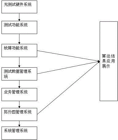
[0038] figure 1 It is a kind of optical network dynamic monitoring system based on GIS technology of the present invention, such as figure 1 As shown, an optical network dynamic monitoring system based on GIS technology includes an optical test hardware system, a test function system, a fault function system, a test data management system, a business management system, a topology map management system, and a system management system. The optical test hardware system includes OTDR equipment, an optical switch and a station computer; the test function system includes a basic test function module, a remote optical switch control module; the fault function system includes a basic alarm module, an external optical power alarm module, An external transmission network management alarm module, a fault process module, and a fault SMS notification module; the te...


PUM


Abstract

The invention relates to a dynamic optical network monitoring system based on GIS technology. The dynamic optical network monitoring system based on the GIS technology is composed of an optical hardware test system, a test function system, a fault function system, a test data management system, a business management system, a topological graph management system and a system management system, optical light intensity in an optical cable is monitored in real time by computer distribution calculation, network communication, automatic measurement, GIS, optical time domain measurement and analysis and other technologies, on, off, abnormal dissipation, potential fault and other states of an optical cable communication network are reflected in time, automatic fault monitoring and automatic positioning of an optical cable network are realized, and reference is provided for removal of faults and hidden troubles, therefore the fault times are reduced, the fault time is shortened, and the communication reliability of the optical cable network is improved.

Description

technical field [0001] The invention relates to a dynamic monitoring system for optical networks based on GIS technology, in particular to a real-time monitoring system for spare cores of optical cables. Background technique [0002] With the development of information technology and people's urgent demand for high-speed data services and image services, and the access of broadband services such as high-speed Internet and multimedia video, my country's optical fiber transmission network continues to develop at a high speed. The construction principle of the optical fiber access network is that the optical fiber is as close as possible to the user, that is, fiber to the curb (FTTC), fiber to the building (FTTB), fiber to the community (FTTZ), fiber to the home (FTTH), which will make the optical cable transmission network become more complex and larger. At the same time, people's requirements for communication quality and service quality will become higher and higher. The d...

Claims


Application Information

Patent Timeline
Patent Type & Authority Applications(China)
IPC IPC(8): H04B10/077
Inventor 张立达陈增铂胡永福
Owner ZHONG FU TONG CO LTD
Learn More