A copper furnace harmful waste gas purification device

An exhaust gas purification device and exhaust gas technology are applied in the direction of furnaces, furnace components, waste heat treatment, etc., which can solve the problems of adverse effects on the surrounding environment, injury to workers, and harmful components escaping into narrow indoor spaces, and achieve the effect of avoiding adverse effects

Active Publication Date: 2019-05-17
全椒金宇粮食机械制造有限公司
View PDF7 Cites 0 Cited by
  • Summary
  • Abstract
  • Description
  • Claims
  • Application Information

AI Technical Summary

Problems solved by technology

[0003] In order to realize the effective utilization of recycled scrap copper, usually compressed recycled copper blocks are added to the melting furnace of the upward continuous casting machine to melt and mix them with the raw material electrolytic copper plates; because compressed recycled copper blocks often contain a small amount of unused To deal with clean insulating wrappings and other organic non-metallic materials, incomplete combustion of organic non-metallic materials in molten copper liquid will form toxic and harmful organic waste gas, which requires a ventilation system to suck toxic and harmful organic waste gas and discharge it into the atmosphere for dilution , to avoid harmful components from escaping into the narrow indoor space and causing harm to the operators, but the harmful components discharged into the atmosphere may also cause adverse effects on the surrounding environment; for this reason, it is necessary to design a harmful exhaust gas purification device for copper furnaces, which can Sufficiently suck and purify toxic and harmful organic waste gas

Method used


Image

  • A copper furnace harmful waste gas purification device
  • A copper furnace harmful waste gas purification device
  • A copper furnace harmful waste gas purification device

Examples


Embodiment Construction

[0014] refer to Figure 1 to Figure 3 , Figure 1 to Figure 3 It is a structural schematic diagram of a specific embodiment of the present invention.

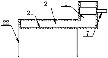
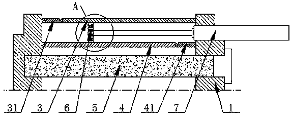
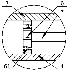
[0015] Such as Figure 1-3 As shown, a harmful exhaust gas purification device for a copper melting furnace includes a harmful exhaust gas exhaust pipe 1, a negative pressure generator is arranged in the harmful exhaust gas exhaust pipe 1, and a plate is arranged at the bottom of the harmful exhaust gas exhaust pipe 1 Shaped air distribution box 2, the bottom of the plate-shaped air distribution box 2 is uniformly provided with some air distribution and suction holes 21; the negative pressure generator includes an upper partition 3 and a lower partition 4, and the upper partition 3 and the The lower partition 4 divides the harmful exhaust gas suction pipe 1 from top to bottom into an upper exhaust part, a middle suction blowing part and a lower suction part. 5, and a piston 6 that can move horizontally and a cylinder 7 that ...


PUM


Abstract

The invention discloses a copper material smelter harmful waste gas purifying device which comprises a harmful waste gas suction pipe. The harmful waste gas suction pipe is internally provided with a negative pressure generator. A platy gas distributing box is arranged at the bottom of the harmful waste gas suction pipe. A plurality of gas distribution and suction holes are evenly formed in the bottom of the platy gas distributing box. The negative pressure generator comprises an upper partition plate and a lower partition plate which sequentially divide the harmful waste gas suction pipe into an exhaust upper portion, a sucking and blowing middle portion and a gas suction lower portion from top to bottom. The exhaust upper portion is communicated with the atmosphere. The gas suction lower portion is provided with an activated carbon filter element. A piston capable of horizontally moving is arranged between the upper partition plate and the lower partition plate. A first check valve is arranged between an exhaust middle portion and the exhaust upper portion. A second check valve is arranged between a gas suction middle portion and the gas suction lower portion. A third check valve is arranged on the piston. Harmful and toxic organic waste gas can be sufficiently sucked and purified.

Description

technical field [0001] The invention relates to the technical field of continuous casting production of oxygen-free copper rods by an upward drawing method, in particular to a device for purifying harmful waste gas from a copper melting furnace. Background technique [0002] Upward-drawing copper continuous casting machine is the upward-drawing oxygen-free copper rod continuous casting unit. The copper upward-drawing continuous casting machine is mainly used to produce long-length bright oxygen-free copper tubes and long-length bright oxygen-free copper flat profiles. The copper upward continuous casting machine can directly use electrolytic copper continuous casting to produce rods, pipes, slabs or other special-shaped materials of different specifications; the copper upward continuous casting machine is divided into 2000 tons, 3000 tons and 4000 tons according to the annual production capacity. ~60000 tons and 8000~12000 tons four grades. Compared with the traditional cop...

Claims


Application Information

Patent Timeline
Patent Type & Authority Patents(China)
IPC IPC(8): B01D53/04B08B15/00F27D17/00
CPCB01D53/04B08B15/00F27D17/008
Inventor 马国红程金春龚义枝
Owner 全椒金宇粮食机械制造有限公司
Why Eureka
Try Eureka