A permanent magnet rail

A technology of guide rails and permanent magnets, applied in tracks, roads, buildings, etc., can solve problems such as inability to form a closed magnetic circuit, incomplete magnetic-gathering structure, and poor magnetic-gathering effect, so as to ensure high-speed operation performance and improve the magnetic-gathering effect , the effect of suppressing the unevenness of the magnetic field

Active Publication Date: 2017-08-25
SOUTHWEST JIAOTONG UNIV
View PDF2 Cites 10 Cited by
  • Summary
  • Abstract
  • Description
  • Claims
  • Application Information

AI Technical Summary

Problems solved by technology

like Image 6 As shown, from the perspective of magnetic flux density distribution, the structure cannot yet form a complete Halbach-type closed magnetic circuit
Rail expansion angle (the cross-sectional view of the expanded guide rail structure is shown in Figure 5 shown by the dotted line in the middle), after the expansion of the track structure, it is equivalent to replacing the permanent magnet with the magnetization direction vertically upward in the Halbach structure with the magnetism-gathering carbon steel, the magnetism-gathering structure is incomplete, and the magnetism-gathering effect is not as good as the Halbach array with a complete structure

Method used


Image

  • A permanent magnet rail
  • A permanent magnet rail
  • A permanent magnet rail

Examples


Embodiment 1

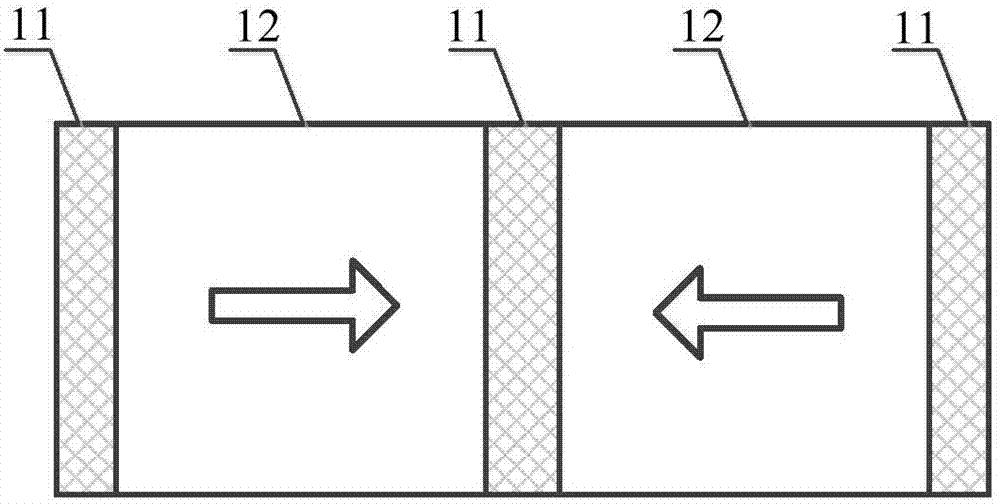
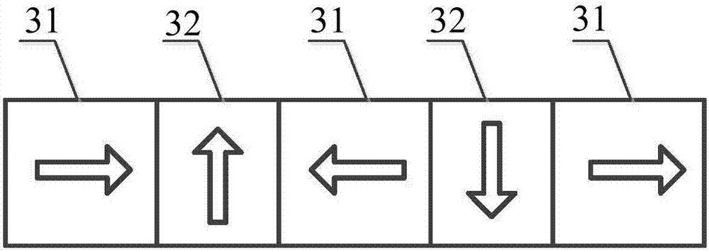
[0064] Embodiment 1. The permanent magnet guide rail is composed of 5 permanent magnets (ie magnetized magnets), including 3 horizontal magnetized magnets and 2 vertical magnetized magnets.

[0065] Figure 7 It is a schematic cross-sectional view of the permanent magnet guide rail in Embodiment 1 of the present invention. like Figure 7 As shown, in the permanent magnet guide rail in the first embodiment, N is 5, that is, the total number of the horizontal magnetization magnets and the vertical magnetization magnets is 5 pieces.

[0066] For example, if Figure 7 As shown, the permanent magnet guide rail is composed of 5 pieces of magnetized magnets 71-75 and 2 pieces of carbon steel 76 and 77. Among them, 71, 73 and 75 are horizontal magnetization magnets, 72 and 74 are vertical magnetization magnets, the horizontal magnetization magnets and the vertical magnetization magnets are arranged at intervals, and carbon steel 76 and 77 are arranged on the vertical magnetization ...

Embodiment 2

[0072] Embodiment 2. The permanent magnet guide rail is composed of 5 permanent magnets (ie magnetized magnets), including 2 horizontal magnetized magnets and 3 vertical magnetized magnets.

[0073] Figure 9 It is a schematic cross-sectional view of the permanent magnet guide rail in the second embodiment of the present invention. like Figure 9 As shown, in the permanent magnet guide rail in the second specific embodiment, N is 5, that is, the total number of the horizontal magnetization magnets and the vertical magnetization magnets is 5 pieces.

[0074] For example, if Figure 9 As shown, the permanent magnet guide rail is composed of 5 pieces of magnetized magnets 91-95 and 3 pieces of carbon steel 96, 97 and 98. Among them, 91, 93 and 95 are vertical magnetization magnets, 92 and 94 are horizontal magnetization magnets, the horizontal magnetization magnets and vertical magnetization magnets are arranged at intervals, and carbon steel 96, 97 and 98 are arranged on the ...


PUM


Abstract

The invention discloses a permanent magnet guide rail. The permanent magnet guide rail comprises: a horizontal magnetization magnet, a vertical magnetization magnet and carbon steel; the horizontal magnetization magnet and the vertical magnetization magnet are spaced apart and closely arranged; a piece of carbon steel is arranged above each vertical magnetization magnet, and The sum of the thickness of the vertical magnetization magnet and the thickness of the carbon steel is equal to the thickness of the horizontal magnetization magnet; Arranged in such a way that the density is the largest and the magnetic flux density under the guide rail is the smallest. By using the permanent magnet guide rail provided by the present invention, the magnetic concentration effect of the permanent magnet guide rail can be improved, so that most of the magnetic lines of force can be gathered to the working area above the guide rail, and the ride comfort and vehicle safety of the permanent magnet guide rail along the driving direction can be effectively improved. operational reliability.

Description

technical field [0001] The invention relates to a high-temperature superconducting magnetic levitation technology, in particular to a permanent magnet guide rail. Background technique [0002] Compared with the electromagnetic levitation (EMS) and electrodynamic levitation (EDS) technologies based on electromagnetic attraction and repulsion, the high-temperature superconducting magnetic levitation technology relies on the magnetic flux pinning between the high-temperature superconductor bulk and the external magnetic field to achieve self-sustaining Stable suspension. This technology does not require active control and has a simple structure, so it has become one of the ideal choices for practical magnetic levitation technology. Limited by the special requirements of the high-temperature superconducting maglev system, the external magnetic field excitation provided by the permanent magnet needs to meet the high magnetic flux density and magnetic field gradient in the cross-...

Claims


Application Information

Patent Timeline
Patent Type & Authority Patents(China)
IPC IPC(8): E01B25/32
CPCE01B25/32
Inventor 邓自刚孙睿雪郑珺司帅帅
Owner SOUTHWEST JIAOTONG UNIV
Why Eureka
Try Eureka