
A flexible anchor

A kind of bolt and flexible technology, applied in the direction of bolt installation, mining equipment, earthwork drilling, etc., can solve the problems of loss of performance, complicated installation, reduced bolt strength, etc., to improve strength and elongation, and strong environmental adaptability , Improve the effect of anchoring performance

Active Publication Date: 2019-01-15
CHINA UNIV OF MINING & TECH (BEIJING)
View PDF5 Cites 0 Cited by
  • Summary
  • Abstract
  • Description
  • Claims
  • Application Information

AI Technical Summary

Problems solved by technology

[0005] At present, through the improvement of anchor rods, such as the appearance of expansion anchor rods, expansion-extensible long anchor rods, pipe-slit anchor rods, elastic flexible anchor rods, etc., these anchor rods have their own defects to a certain extent: one is Expansion anchors are often realized by special materials, which are costly and reduce the effective cross-sectional size of the anchor, reducing the strength of the anchor; the second is that the expansion and elongation of the long anchor is connected with special pipe fittings. Once the pipe fails, the anchor will be broken. Lost its own performance; Third, some anchor rods are difficult to construct on site and cannot reach the effective anchoring range
For full-length anchor bolts and end anchor bolts, the installation is complicated during on-site construction, and the construction period is long; it cannot compensate the anchor hole changes caused by the movement of the rock formation, especially the support of soft rock and large deformation roadways. protection problem; the anchoring force of the anchor rod is single, once the expansion force is not enough, the anchor rod will slip off

Method used


Image

  • A flexible anchor
  • A flexible anchor
  • A flexible anchor

Examples


Embodiment Construction

[0030] Typical embodiments embodying the features and advantages of the present invention will be described in detail in the following description. It should be understood that the invention is capable of various changes in different embodiments without departing from the scope of the invention, and that the description and illustrations therein are illustrative in nature and not limiting. this invention.

[0031] In the following description, numerous specific details are given in order to provide a more thorough understanding of the present invention. It will be apparent, however, to one skilled in the art that the present invention may be practiced without one or more of these details. In other examples, some technical features known in the art are not described in order to avoid confusion with the present invention.

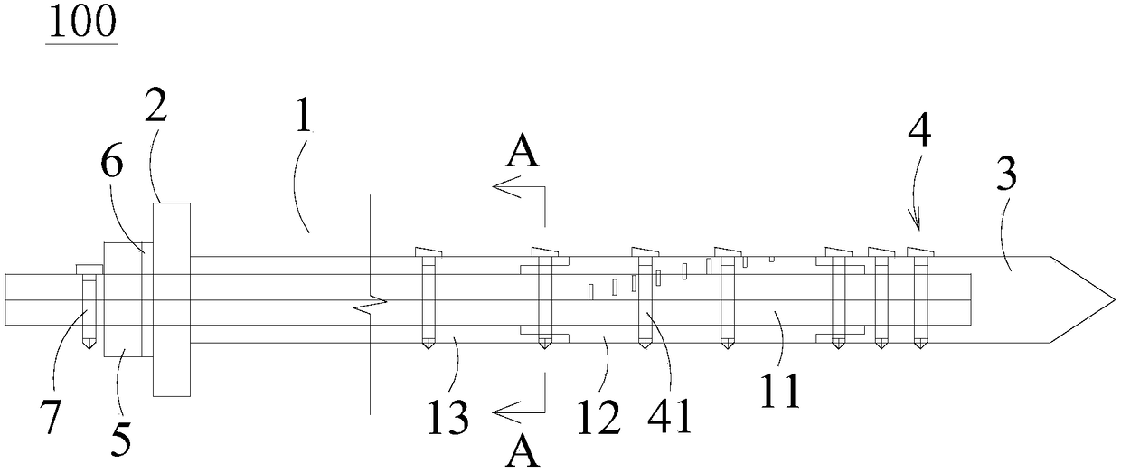
[0032] figure 1 It is a schematic diagram of a flexible anchor rod according to an embodiment of the present invention, please refer to figure 1 , the fl...


PUM


Abstract

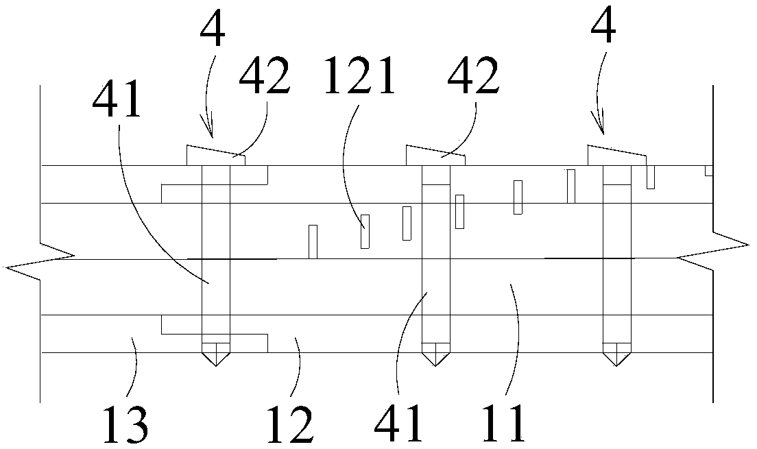
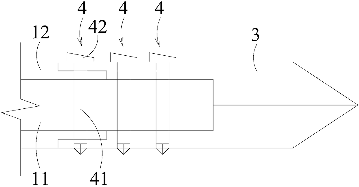
The invention discloses a flexible anchor rod. The flexible anchor rod comprises a rod body, a tray and a head, wherein the tray and the head are arranged at the two ends of the rod body correspondingly. The tray is detachably installed at one end of the rod body. The head is arranged at the other end of the rod body through at least one anti-disengagement device. The rod body comprises a flexible metal core, a first sleeve and a second sleeve, wherein the first sleeve and the second sleeve are arranged outside the flexible metal core in a coating mode. The first sleeve and the second sleeve are sequentially arranged on the outer side of the flexible metal core in a coating and spaced mode and are fixed to the flexible metal core through one or more anti-disengagement devices. According to the flexible anchor rod, the flexible metal core is used, and the purposes that the strength and the elongation rate of the anchor rod are improved, and the length of the anchor rod can be freely changed according to different conditions are achieved; and the two-sleeve design is adopted, the friction force of the anchor rod and surrounding rock can be significantly improved through the humid environment of a mine, and anchor disengagement can be effectively prevented.

Description

technical field [0001] The invention relates to an anchor rod, in particular to a flexible anchor rod. Background technique [0002] Bolt is the main form of support in mines. During its development, various deformations have occurred, such as grouting bolts, self-drilling bolts, glass fiber reinforced plastic bolts, resin bolts, etc. However, in the process of actual application on site, due to factors such as insufficient tensile strength and poor shear resistance of the bolt itself, it is easy to fail, which poses a great threat to mine safety production and seriously affects normal production. Enterprises bring huge economic losses. In the support process of mine roadway, according to different situations and positions, the combined support forms such as bolt-shotcrete, bolt-protective net-cable, bolt-grouting-protective net-cable are often used. However, in roadways with high surrounding rock stress, large crushing range, and severe floor separation, the ideal anchori...

Claims


Application Information

Patent Timeline
Patent Type & Authority Patents(China)
IPC IPC(8): E21D21/00
CPCE21D21/0033
Inventor 郭鹏飞杨军
Owner CHINA UNIV OF MINING & TECH (BEIJING)
Learn More