
Probe of electrical vortex sensor and electrical vortex sensor

An eddy current sensor and cable technology, applied in instruments, electrical devices, electromagnetic means, etc., can solve the problems of the sensor detection displacement sensitivity and linear range reduction, low compensation accuracy, long sensor probe length, etc., to ensure the detection of displacement. Sensitivity, reduced probe size, reduced effects of eddy current field effects

Inactive Publication Date: 2016-07-27
ZHUHAI GREE REFRIGERATION TECH CENT OF ENERGY SAVING & ENVIRONMENTAL PROTECTION
View PDF6 Cites 9 Cited by
  • Summary
  • Abstract
  • Description
  • Claims
  • Application Information

AI Technical Summary

Problems solved by technology

[0003] The application temperature range of conventional eddy current sensors on the market is only within 0-90°C, which cannot meet the non-contact measurement requirements of some high temperature occasions
The current temperature compensation method used to solve the above problems includes adding a temperature compensation coil in the probe of the eddy current sensor as a reference for the detection coil. The difference between the two coils does not change as the temperature changes, so temperature compensation can be carried out effectively. , due to the introduction of the temperature compensation coil as the compensation reference of the detection coil, the temperature compensation coil will also generate an electromagnetic field, which will affect the magnetic field in the detection coil, resulting in a decrease in the sensor's probe detection displacement sensitivity and linear range, such as detection After a certain distance between the coil and the temperature compensation coil, the mutual influence of the two coils can be reduced, but the length of the sensor probe will be longer when the distance between the two coils is larger, which is not conducive to displacement detection in a small space
For another example, the temperature compensation of the eddy current displacement sensor is carried out in the front processor for algorithm compensation, and the compensation accuracy of this method is low

Method used


Image

  • Probe of electrical vortex sensor and electrical vortex sensor
  • Probe of electrical vortex sensor and electrical vortex sensor
  • Probe of electrical vortex sensor and electrical vortex sensor

Examples


Embodiment 1

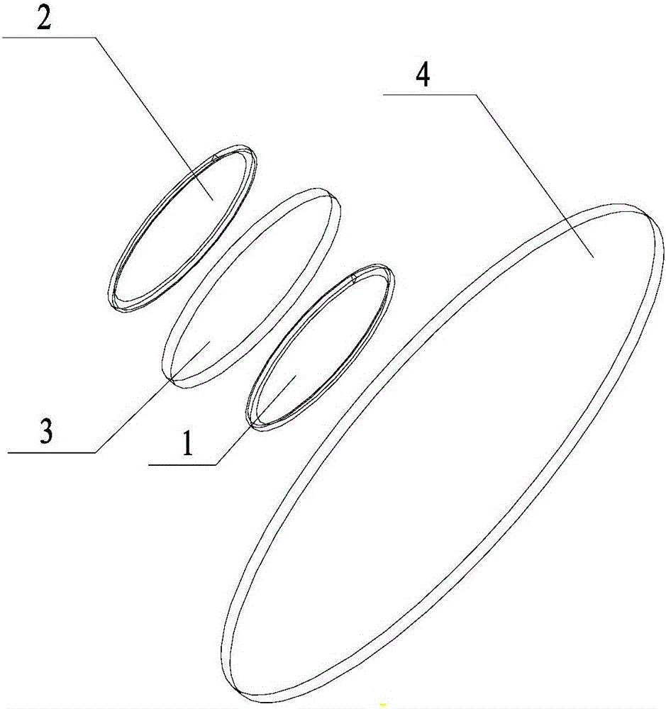
[0019] figure 1 It is a schematic diagram of the position of the coil in the probe of an eddy current sensor provided by Embodiment 1 of the present invention. This embodiment is applicable to the situation where the size of the probe is reduced on the basis of ensuring the detection accuracy, and specifically includes: detection coil 1, temperature compensation coil 2 and a magnetic isolation plate 3; the magnetic isolation plate 3 is arranged between the detection coil 1 and the temperature compensation coil 2, and is parallel to the detection coil 1 and the temperature compensation coil 2 respectively.

[0020] According to Faraday's law of electromagnetic induction, when the detection coil 1 in the probe passes a sinusoidal alternating current i 1 , the space around the detection coil 1 will inevitably produce a sinusoidal alternating magnetic field H 1 , it causes the surface of the measured metal conductor placed in this magnetic field to generate an induced current, th...

Embodiment 2

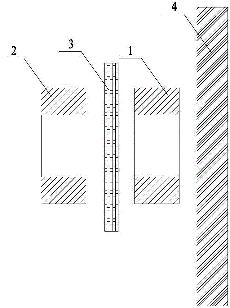
[0025] figure 2 It is a cross-sectional view of the position of the coil in the probe of an eddy current sensor in the second embodiment of the present invention. On the basis of the above-mentioned embodiments, the technical solution of this embodiment further limits the specific positions of the detection coil 1 and the temperature compensation coil 2, specifically including: the detection coil 1 and the temperature compensation coil 2 are related to the magnetic isolation Plate 3 is mirror symmetrical. When winding the coil, the same bundle of enameled wires can be wound on the frame according to the set rules by a winding machine to form the detection coil 1 and the temperature compensation coil 2 . Wherein, the set rules may be parameters manually input to the winding machine, including the number of turns of the coil, the winding method, and the distance between the coils. The advantage of such a design is to effectively ensure the consistency of parameters between th...

Embodiment 3

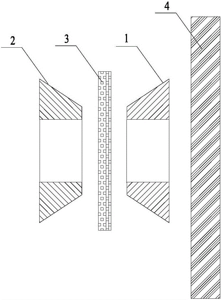
[0027] image 3It is a sectional view of the coil position in the probe of another eddy current sensor in the third embodiment of the present invention. On the basis of the above-mentioned embodiments, the technical solution of this embodiment further defines the specific shapes of the detection coil 1 and the temperature compensation coil 2, specifically including: the cross section of the detection coil 1 along the direction of the central axis is trapezoidal, and the trapezoidal The distance between the bottom surface and the detection surface is smaller than the distance between the top surface of the trapezoid and the detection surface. Although the magnetic isolation plate 3 is set between the detection coil 1 and the temperature compensation coil 2, it can isolate the magnetic field of the temperature compensation coil 2 and the magnetic field of the detection coil 1, but the electromagnetic isolation effect of the magnetic isolation plate 3 will be affected by the temp...


PUM


Abstract

The invention discloses a probe of an eddy current sensor and the eddy current sensor. The probe of the eddy current sensor includes a detection coil, a temperature compensation coil and a magnetic isolation plate; the magnetic isolation plate is arranged between the detection coil and the temperature compensation coil, and is respectively connected to the detection coil and the temperature The compensation coils are parallel. The invention solves the problem that the temperature compensation precision of the current eddy current sensor is increased at the cost of increasing the probe, realizes reducing the probe size on the basis of ensuring the compensation precision, and achieves the effect of ensuring the detection displacement sensitivity and reducing the probe size.

Description

technical field [0001] Embodiments of the present invention relate to distance measuring equipment, and in particular to a probe of an eddy current sensor and the eddy current sensor. Background technique [0002] The eddy current sensor has been widely used in the detection field due to its non-contact, large measurement range, high sensitivity, simple structure, and not affected by non-metallic materials. [0003] The application temperature range of conventional eddy current sensors on the market is only within 0-90°C, which cannot meet the non-contact measurement requirements of some high temperature occasions. The current temperature compensation method used to solve the above problems includes adding a temperature compensation coil in the probe of the eddy current sensor as a reference for the detection coil. The difference between the two coils does not change as the temperature changes, so temperature compensation can be carried out effectively. , due to the introdu...

Claims


Application Information

Patent Timeline
Patent Type & Authority Applications(China)
IPC IPC(8): G01B7/02
CPCG01B7/02
Inventor 刘志昌黄伟才叶俊奇耿继青
Owner ZHUHAI GREE REFRIGERATION TECH CENT OF ENERGY SAVING & ENVIRONMENTAL PROTECTION
Learn More