Ambient light self-adaption method and apparatus for infrared touch screen

An infrared touch screen and ambient light technology, which is applied in the input/output process of data processing, instruments, electrical digital data processing, etc., can solve the problems of non-representative sampling and uneven distribution of light intensity, and achieve non-representative sampling Effects of issues, savings, and number of ambient light samples

Inactive Publication Date: 2016-07-27
HITEVISION CO LTD
View PDF7 Cites 2 Cited by
  • Summary
  • Abstract
  • Description
  • Claims
  • Application Information

AI Technical Summary

Problems solved by technology

In the method disclosed by the present invention, each receiving tube corresponds to a plurality of transmitting tubes in multiple emitting areas through the multiplexed lamp tube arrangement scheme of receiving tubes, and only the infrared emitting areas that are or are about to perform infrared scanning need to be scanned. The corresponding few sparsely arranged receiving tubes are sampled to complete the sample-holding and subtraction operations of the transmitting area. Since the number of receiving tubes is far less than the corresponding transmitting tubes, the number of capacitors and the number of ambient light sampling times are saved. Simultaneously, because the present invention has all carried out ambient light sampling storage to each emission tube before scanning, thereby solved the non-representative problem of sampling brought by the uneven distribution of ambient light intensity

Method used


Image

  • Ambient light self-adaption method and apparatus for infrared touch screen
  • Ambient light self-adaption method and apparatus for infrared touch screen
  • Ambient light self-adaption method and apparatus for infrared touch screen

Examples


Embodiment 1

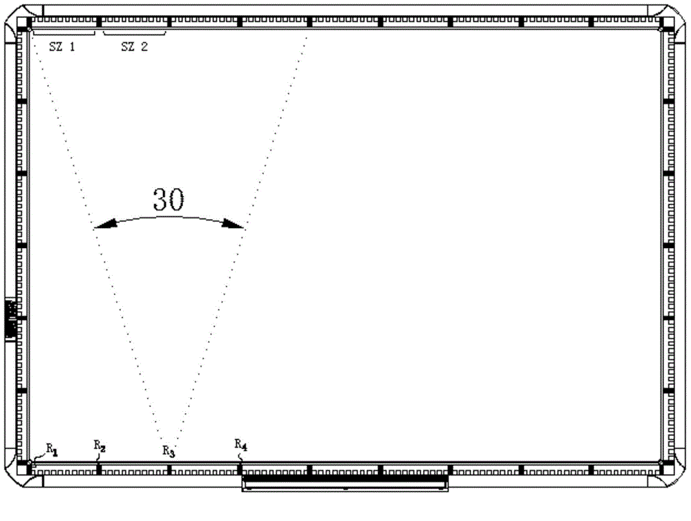
[0031] figure 2 It is the structure diagram of the infrared touch screen of the preferred embodiment 1. As mentioned above, any receiving tube R 3 The effective working angle can cover the four infrared emitting areas on the opposite frame, and any infrared emitting area is covered by at least three infrared receiving tubes on the opposite frame (the edges are three due to grid defects, and the middle is four) Covered by the effective "field of view". Compared with the prior art, in this embodiment, only 4 receiving tubes are used for 10 infrared emitting tubes in a transmitting area, and only 4 receiving tubes can be set in the corresponding sample and hold circuit. 1 -C 4 , Saving the number of holding capacitors and reducing the point of failure. At the same time, since the ambient light sampling is performed on each receiving tube multiple times, the problem of light interference that occurs in the prior art due to the unrepresentative ambient light sampling does not occur....

Embodiment 2

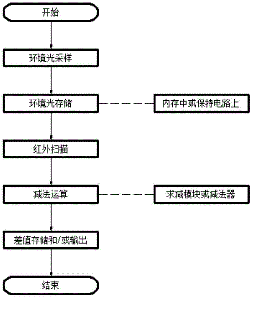
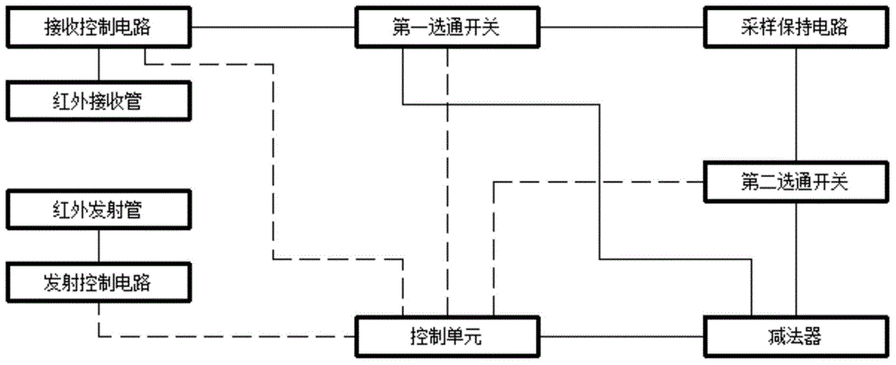
[0038] Figure 4 Is a schematic diagram of the infrared frame structure of the preferred embodiment 2 of the present invention, Figure 5 It is a functional block diagram of the software implementation method of this embodiment (the dotted line represents the control signal, and the solid line represents the data signal).

[0039] Figure 4 The medium black square represents the receiving tube. There are 24 infrared emitting tubes between any two black squares. The receiving and sending tubes on the Y axis and the infrared emitting tubes on the X axis are omitted in the figure. Looking at the picture, an infrared emitting area is formed between any two adjacent receiving tubes. Each infrared emitting area is covered by the effective receiving angles of multiple receiving tubes on the opposite frame. The infrared frame includes infrared emitting circuits and infrared. Receiving circuit and control unit. The control unit (control chip, single-chip microcomputer, MCU) includes at le...


PUM


Abstract

The invention discloses an ambient light self-adaption method applied to an infrared touch screen with a touch screen and an infrared bezel. The touch screen is used for receiving a touch input; the infrared bezel is used for detecting coordinates of touch points and is arranged at the periphery of the touch screen; infrared emission diodes and infrared receiving diodes are arranged on any edge of the infrared bezel; the infrared emission diodes are densely distributed; the infrared receiving diodes are sparsely distributed; an infrared emission region is formed between the two infrared receiving diodes on any edge of the infrared bezel; and the emission diodes in each emission region are covered with an effective receiving angle of at least two receiving diodes on the opposite bezel. The method is characterized by comprising a step of acquiring ambient light when each infrared emission region is subjected to infrared scanning, a step of storing the ambient light, a step of performing infrared scanning, a step of calculating a difference value and a step of storing and/or outputting an effective signal. Therefore, the circuit size is reduced and the situation of unrepresentative ambient light sampling is avoided.

Description

Technical field [0001] The invention discloses an ambient light adaptive method and device for an infrared touch screen. technical background [0002] The industry's anti-light interference methods for infrared touch screens can be divided into pre-processing and post-processing. The former mainly uses a light filter device similar to a filter to filter out the ambient light entering the receiving tube or uses a special frame structure or circuit structure to block or shield the ambient light to reduce the intensity of the ambient light received by the receiving tube , To achieve the purpose of reducing light interference. Post-processing generally adopts a special circuit structure to process the signals collected in the infrared scanning, recording the intensity of the ambient light through the sample-and-hold circuit, and then subtracting the infrared scanning signal and the signal recorded in the sample-and-hold circuit through the subtraction circuit. Finally, a "pure" inf...

Claims


Application Information

Patent Timeline
Patent Type & Authority Applications(China)
IPC IPC(8): G06F3/042
Inventor 杨长亮罗顺喜周雷强
Owner HITEVISION CO LTD
Why Eureka
Try Eureka