
Transmission electron microscope sample table for observing three-dimensional atom probe test sample

A transmission electron microscope sample and atom probe technology, which is applied to circuits, discharge tubes, electrical components, etc., can solve the problems of low success rate, inconvenient operation, and small application range, and achieve the effect of convenient operation and one-handed operation.

Active Publication Date: 2016-07-27
NANJING UNIV OF SCI & TECH
View PDF5 Cites 13 Cited by
  • Summary
  • Abstract
  • Description
  • Claims
  • Application Information

AI Technical Summary

Problems solved by technology

[0004] The above method is only suitable for the JEOL electron microscope in Japan, which has a small scope of application and has the following defects: (1) The operation is inconvenient. The sample installation process requires multiple hands to work at the same time. It is easy to be damaged, and the success rate is very low; (2) the sample rod cannot be tilted at a large angle, and only the two-dimensional shape of the nano-tip can be obtained, but the three-dimensional high-resolution image of the nano-tip cannot be obtained. Transmission electron microscopy and three-dimensional atomic Probe results are not true 3D space fits

Method used


Image

  • Transmission electron microscope sample table for observing three-dimensional atom probe test sample
  • Transmission electron microscope sample table for observing three-dimensional atom probe test sample
  • Transmission electron microscope sample table for observing three-dimensional atom probe test sample

Examples


Embodiment

[0050] In this embodiment, an improvement is made on the sample rod body 1 of the existing transmission electron microscope sample rod. The above-mentioned structure is adopted, and two guide rods are provided for independent processing, and then inserted into the slot of the sample rod body by interference fit. The maximum outer edge distance between two guide rails is 4.3mm, the guide rail width is 1mm, and the height is 1mm. The notches for the clamp and eccentric are 13mm long and 2.5mm wide, and run from the top of the sample holder body all the way to the center. In order to facilitate the smooth movement of the pressing block up and down, a semi-cylindrical tail that matches the width and height of the notch is added to the rear end of the notch. At the bottom of the notch, a circular arc-shaped bottom groove and a rectangular step are designed according to the shape and size of the sample-carrying copper tube and the professional clamping platform, so as to position th...


PUM


Abstract

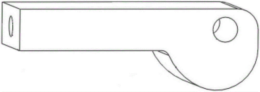
The invention relates to a transmission electron microscope sample table for observing a three-dimensional atom probe test sample. The transmission electron microscope sample table comprises a sample rod main body, a press part, an automatic reset device and guide rails, wherein the guide rails are connected to one end of the sample rod main body, a groove opening is formed in the end of the sample rod main body, an arc bottom groove is formed in the axial center of the groove opening, a rectangular step is arranged at the groove opening of the bottom groove, a stepped through hole is formed in the tail end of the bottom groove, the press part comprises a press block and an eccentric wheel, the eccentric wheel is used for pressing the press block, an arc groove body is formed in the press block, is symmetric to the bottom groove of the sample rod main body and has the same shape as the bottom groove, a guide boss of the press block is arranged in the stepped through hole, the automatic reset device is a spring, and the guide boss passes through the spring. The transmission electron microscope sample table is simple in structure and is convenient to process and maintain, large-angle rotation in an inclination way can be achieved, the three-dimensional atom probe test sample can be directly loaded, the transmission electron microscope sample table can be used as a three-dimensional reconstruction sample rod of a transmission electron microscope, and the acquired transmission electron microscope image can be used for directly correcting a data reconstruction result of a three-dimensional atom probe.

Description

technical field [0001] The invention relates to a transmission electron microscope sample stage for observing the three-dimensional shape and structure of a three-dimensional atom probe sample, which belongs to a three-dimensional space characterization method combining nanometer material micro-region shape, composition and atomic structure. Background technique [0002] As an important means of characterization, transmission electron microscopy is widely used in the fields of material science and life science, and is famous for "seeing with your own eyes" and "real-time observation". Transmission electron microscopy is usually used to observe the two-dimensional morphology of nanomaterials, structure projection and analysis of micro-region components. Its resolution in two-dimensional space reaches the sub-angstrom level, and the atomic column of the material structure in a specific orientation can be clearly observed. projection. With the development of super energy spect...

Claims


Application Information

Patent Timeline
Patent Type & Authority Applications(China)
IPC IPC(8): H01J37/20
CPCH01J37/20
Inventor 刘吉梓沙刚
Owner NANJING UNIV OF SCI & TECH
Learn More