

Polarized microwave thermoacoustic imaging device and method
A thermoacoustic imaging and microwave technology, which is used in measurement devices, analysis of solids using sonic/ultrasonic/infrasonic waves, and material analysis using sonic/ultrasonic/infrasonic waves to achieve broad application prospects.
- Summary
- Abstract
- Description
- Claims
- Application Information
AI Technical Summary
Problems solved by technology
Method used
Image

Examples
Embodiment 1
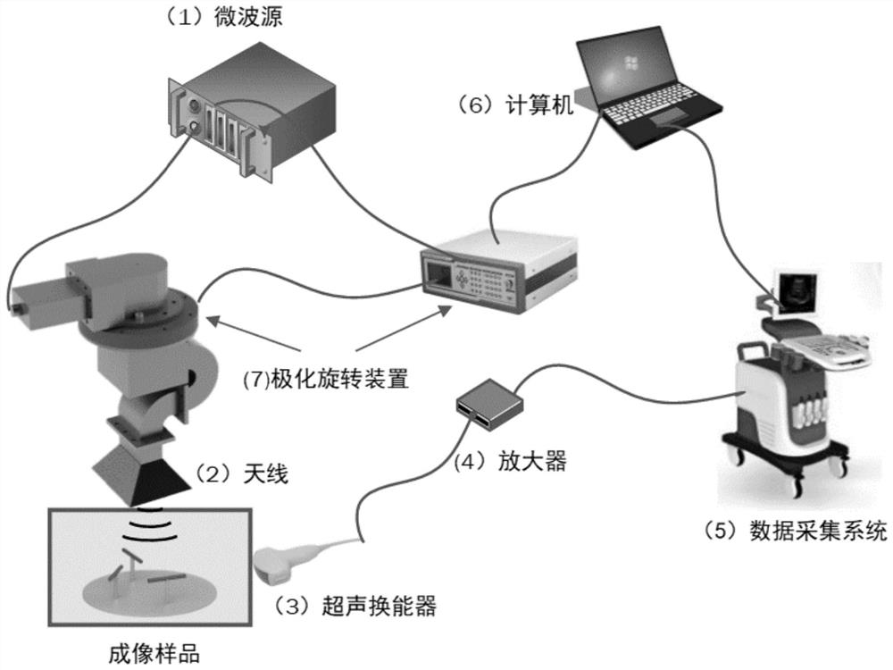
[0043] Such as figure 1 As shown, the polarized microwave thermoacoustic imaging device includes a microwave generator and a thermoacoustic signal acquisition and imaging device; the microwave generator includes a microwave source (1) and an antenna (2); the thermoacoustic signal acquisition and imaging device Including an ultrasonic transducer (3), an amplifier (4), a data acquisition system (5), a computer (including image reconstruction software) (6) and a polarization rotation device (7);
[0044]The microwave source (1) is used to generate a microwave signal of a specific frequency; the antenna (2) irradiates the microwave signal to the imaging area, thereby exciting the imaging sample to generate a thermoacoustic signal; the ultrasonic transducer (3) uses for receiving and collecting thermoacoustic signals generated by imaging samples; the amplifier (4) amplifies the received thermoacoustic signals; the data acquisition system (5) is used for data processing and analysis...
Embodiment 2
[0048] Corresponding to the device in the above-mentioned embodiment 1, this embodiment provides a polarized microwave thermoacoustic imaging method, including the following steps:
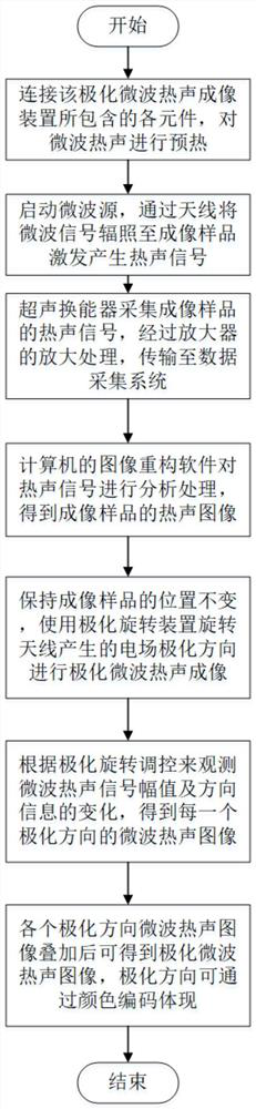
[0049] S1. Connect the components included in the polarized microwave thermoacoustic imaging device to preheat the microwave thermoacoustic;
[0050] S2. Start the microwave source, and irradiate the microwave signal to the imaging sample through the antenna to generate a thermoacoustic signal;
[0051] S3. The thermoacoustic signal of the imaging sample is collected by the ultrasonic transducer, amplified by the amplifier, transmitted to the data acquisition system, collected and stored in the computer;
[0052] S4. Analyzing and processing the thermoacoustic signal through the image reconstruction software of the computer, so as to obtain the thermoacoustic image of the imaging sample.
[0053] S5. Keep the position of the imaging sample unchanged, and use the polarization rotation device to ro...
Embodiment 3
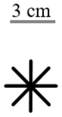
[0056] In this embodiment, microwave thermoacoustic simulation imaging is carried out on a model in the shape of "米" by using the above-mentioned device and method. The internal filling medium of the model is edible soy sauce. The model parameters are that the length of a single cylinder is 3cm, and the radius of the bottom surface of the cylinder is 1mm. The simulation results obtained imaging results of four different polarization angles and the superposition of microwave thermoacoustic images in each polarization direction. Polarized microwave thermoacoustic images can be obtained, such as Figure 3-8 shown, where image 3 is the model diagram of the "m"-shaped model, Figure 4-8 Corresponding to 0 degree, 45 degree, 90 degree, 135 degree and the superimposed image of the four respectively. According to the results of thermoacoustic imaging, it can be found that for linearly polarized electromagnetic waves, the thermoacoustic signals generated for objects are as follows: ...
PUM
| Property | Measurement | Unit |
|---|---|---|
| Base radius | aaaaa | aaaaa |
Abstract
Description
Claims
Application Information