Miniature low-profile broadband dual-circular-polarization microstrip antenna

A dual circular polarization and microstrip antenna technology, applied in the field of communication and navigation, can solve the problems of increased antenna height, poor antenna circular polarization characteristics, and lack of broadband characteristics, so as to reduce the quality factor and widen the working frequency band , circular polarization performance good effect

Active Publication Date: 2016-07-27
NO 54 INST OF CHINA ELECTRONICS SCI & TECH GRP
View PDF8 Cites 30 Cited by
  • Summary
  • Abstract
  • Description
  • Claims
  • Application Information

AI Technical Summary

Problems solved by technology

[0003] After patent retrieval, the relevant patents closely related to the present invention are as follows: Patent No.: CN200810114878.2, circular polarization broadband capacitance compensation probe feed stacked microstrip antenna array, through stacked structure and capacitance compensation probe technology Achieved a standing wave bandwidth greater than 20%, but only achieved single circular polarization; patent number: CN201010521963.8, a single-feed wideband circularly polarized laminated microstrip antenna and its feeding device, realized through a laminated structure 15.6% of the 3dB axial ratio bandwidth, and the antenna height > 0.14λ 0 ;Patent No.: CN201310444387.5, UHF frequency band dual-band circularly polarized low-profile air microstrip antenna, capable of dual-band operation, without broadband characteristics; Patent No.: CN201420045812.3, high-bandwidth dual-polarized microstrip antenna, The working frequency ba...

Method used


Image

  • Miniature low-profile broadband dual-circular-polarization microstrip antenna
  • Miniature low-profile broadband dual-circular-polarization microstrip antenna
  • Miniature low-profile broadband dual-circular-polarization microstrip antenna

Examples


Embodiment Construction

[0029] The present invention will be further described below in conjunction with the accompanying drawings.

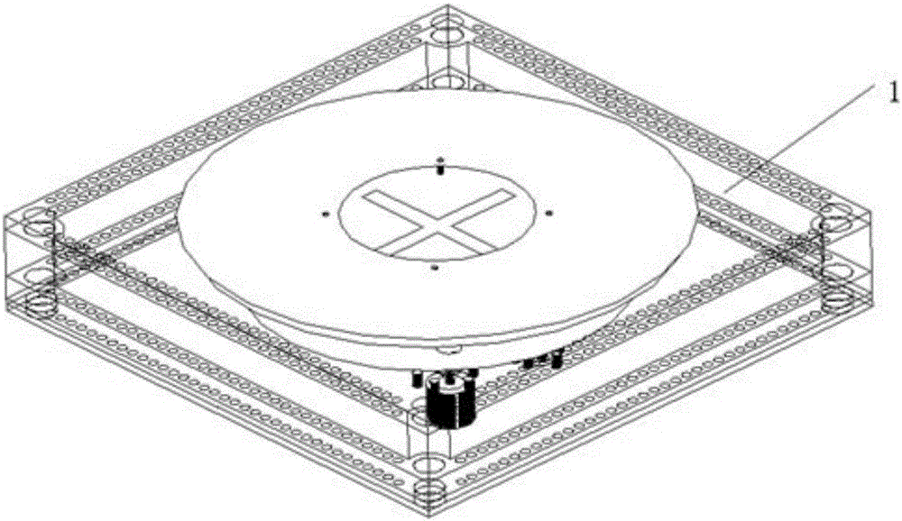
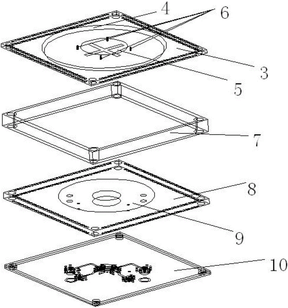
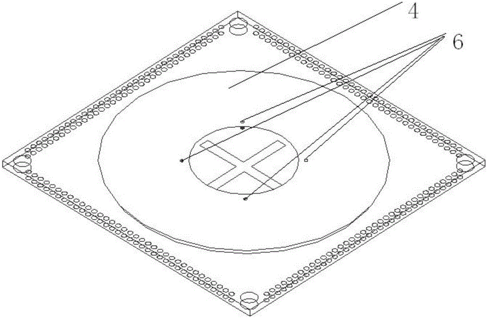
[0030] A miniaturized low-profile broadband dual circularly polarized microstrip antenna, such as figure 1 As shown, it is a layered structure. The miniaturized low-profile broadband dual-circularly polarized microstrip antenna 1 is arranged sequentially from top to bottom: a first dielectric substrate 3, a metal support frame 7, a second dielectric substrate 8 and a third dielectric substrate 10, such as figure 2 As shown; the first dielectric substrate 3 is composed of an upper copper clad layer, an intermediate dielectric and a lower copper clad layer; the second dielectric substrate 8 is composed of an upper surface copper clad layer and a dielectric plate; the third dielectric substrate 10 is composed of an upper copper clad layer, a middle strip-shaped The wire, the lower copper-clad layer and two layers of dielectric, the upper copper-clad layer and the middle...


PUM


Abstract

The invention discloses a miniature low-profile broadband dual-circular-polarization microstrip antenna.The antenna is composed of a first dielectric substrate, a metal supporting frame, a second dielectric substrate and a third dielectric substrate.Parasitic metal surface-mounted devices are arranged on the upper surface and the lower surface of the first dielectric substrate, the surface-mounted device on the upper surface is larger than the surface-mounted device on the lower surface in size, and the surface-mounted devices are connected through four metalized through holes; a feed surface-mounted device is arranged on the upper surface of the second dielectric substrate; the third dielectric substrate comprises four strip lines, a 90-degree bridge, two feed probes and two radio frequency coaxial connectors.The 90-degree bridge and dual-feed technologies are adopted for realizing dual circular polarization, a laminated structure and a dual-parasitic surface-mounted device structure connected through the metalized through holes are adopted comprehensively to expand the bandwidth of the microstrip antenna, so that the bandwidth of the antenna reaches 19.4%, and the circular polarization ratio within the frequency band range is smaller than 1.3 dB; the antenna has miniature low-profile characteristics, and the size is 0.45 lambda0*0.45 lambda0*0.075 lambda0.

Description

technical field [0001] The invention relates to antenna technology in the field of communication and navigation, in particular to a miniaturized low-profile wide-band dual circularly polarized microstrip antenna. The invention is suitable as an array element of a phased array antenna, so it is suitable for occasions requiring relatively high bandwidth and circular polarization performance in vehicle-mounted, airborne and other low-profile satellite mobile communications. Background technique [0002] Microstrip antenna has the advantages of low profile, light weight and low cost, etc., but its inherent narrow-band characteristics (generally less than 5% relative bandwidth) limit its application range. People have adopted many techniques to widen the bandwidth of the microstrip antenna, such as the use of irregular metal patch, laminated structure and other measures. However, it is difficult to design with irregular metal patches, and often affects the polarization performan...

Claims


Application Information

Patent Timeline
IPC IPC(8): H01Q1/38H01Q1/50H01Q1/12
CPCH01Q1/12H01Q1/38H01Q1/50
Inventor 张宙韩国栋王焕菊何应然张领飞肖松武伟贾丹卢炜丁宁陈斌
Owner NO 54 INST OF CHINA ELECTRONICS SCI & TECH GRP
Why Eureka
Try Eureka