Rotor structure for high speed permanent magnet synchronous machine

A permanent magnet synchronous motor and rotor structure technology, applied in the synchronous machine parts, magnetic circuit shape/style/structure, magnetic circuit rotating parts, etc. The difficulty of heat dissipation, the effect of reducing eddy current loss and low eddy current loss

Inactive Publication Date: 2016-07-27
CHONGQING UNIV
View PDF4 Cites 11 Cited by
  • Summary
  • Abstract
  • Description
  • Claims
  • Application Information

AI Technical Summary

Problems solved by technology

[0008] The purpose of the present invention is to provide a high-speed permanent magnet synchronous motor rotor structure, aiming to solve the problem of large eddy current loss of the permanent magnet synchronous motor rotor

Method used


Image

  • Rotor structure for high speed permanent magnet synchronous machine
  • Rotor structure for high speed permanent magnet synchronous machine
  • Rotor structure for high speed permanent magnet synchronous machine

Examples


Embodiment Construction

[0022] The present invention will be further described below in conjunction with accompanying drawing:

[0023] see figure 1 :

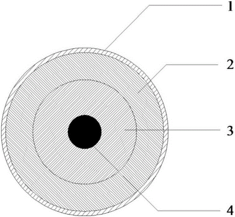
[0024] A high-speed permanent magnet synchronous motor rotor structure, including a motor rotor and a rotating shaft,

[0025] The outermost layer of the motor rotor is the protective layer 1, the rotating shaft 4 is installed in the center of the motor rotor, and the permanent magnet is between the rotating shaft 4 and the protective layer 1; the permanent magnet is divided into inner and outer layers, and the outer permanent magnet is ferrite Permanent magnet 2, the inner permanent magnet is a rare earth permanent magnet 3, the thickness ratio of the two layers of permanent magnets can be designed according to the premise of ensuring the required magnetic field generation capacity and actual needs, the larger the thickness ratio of the ferrite permanent magnet, The smaller the overall residual magnetism of the permanent magnet, the smaller the ed...


PUM


Abstract

The invention discloses a rotor structure for a high speed permanent magnet synchronous machine. The rotor structure comprises an electric machine rotor and a rotating shaft, wherein a protection layer is arranged at the outermost layer of the electric machine rotor; the rotating shaft is arranged at the center of the electric machine rotor; permanent magnets are arranged between the rotating shaft and the protection layer; the permanent magnets are divided into an inner layer and an outer layer; the permanent magnet at the outer layer is a ferrite permanent magnet; the permanent magnet at the inner layer is a rare earth permanent magnet; the number of poles of the ferrite permanent magnet is p1, the number of poles of the rare earth permanent magnet is p2, and P1 is equal to P2; and the central lines of the same poles of the two layers of permanent magnets are coincident. According to the rotor structure, the advantages of residual magnetism and low conductivity of the ferrite permanent magnet and the advantage of high residual magnetism of the rare earth permanent magnet are fully combined, the ferrite permanent magnet and the rare earth permanent magnet are matched according to a certain thickness ratio, so that the vortex loss of the rotor is reduced and the heat dissipation difficulty of the electric machine is reduced on the premise of guaranteeing the needed magnetic field generation ability, and furthermore, through the reasonable design, a problem of large volume of the electric machine, which is caused by entirely using the ferrite permanent magnet material, or large vortex loss of the electric machine, which is caused by entirely using the rare earth permanent magnet material, is solved.

Description

technical field [0001] The invention belongs to the field of motors, in particular to a rotor structure of a high-speed permanent magnet synchronous motor. Background technique [0002] The high-speed motor is directly connected to the high-speed prime mover or load without the need for a transmission device that is difficult to maintain and has a high failure rate, so that the entire transmission system has a series of advantages such as high power density, high efficiency, and low operation and maintenance costs. High-speed machine tools, blowers, high-speed centrifuges, grinding machines, micro gas turbines, flywheel energy storage, electric vehicles and other fields have broad application prospects. Due to its advantages of high efficiency and high power density, permanent magnet synchronous motor has been widely concerned and applied in high-speed motors. However, a series of key problems such as large rotor eddy current loss and serious heat generation have not been w...

Claims


Application Information

Patent Timeline
Patent Type & Authority Applications(China)
IPC IPC(8): H02K1/27H02K1/02
CPCH02K1/2793H02K1/02H02K21/02H02K2213/03
Inventor 沈启平
Owner CHONGQING UNIV
Why Eureka
Try Eureka