
Optical module lighting power control system and control method therefor

A technology of optical power control and optical modules, which is applied in light sources, electric light sources, lighting devices, etc., can solve the problems of relatively large fluctuations in the output optical power of lasers, the inability to maintain constant output optical power, and the inability to adapt to changes in laser characteristics. Work efficiency, burnout prevention effect

Active Publication Date: 2016-07-27
珠海天启技术有限公司
View PDF7 Cites 8 Cited by
  • Summary
  • Abstract
  • Description
  • Claims
  • Application Information

AI Technical Summary

Problems solved by technology

At present, many control circuits use analog control circuits. The circuits need to manually adjust the voltage of the potentiometer to control the output voltage of the laser. This analog control circuit controls the laser by detecting the voltage of the backlight detector of the laser. The output optical power, in the case of high and low temperature, the characteristics of the laser have changed, and the magnification and reference of the analog control circuit are fixed, which cannot adapt to the change of the characteristics of the laser. In this way, in the case of high and low temperature, the output light of the laser The power fluctuation is relatively large, especially at low temperature, the fluctuation can hardly meet the needs of the system, and the output optical power cannot be kept constant

Method used


Image

  • Optical module lighting power control system and control method therefor
  • Optical module lighting power control system and control method therefor
  • Optical module lighting power control system and control method therefor

Examples


Embodiment 1

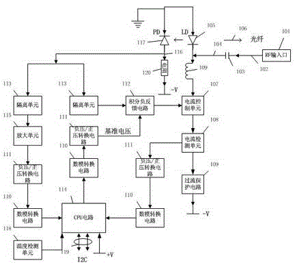
[0045] Implementation of the present invention at first sight figure 2 , mainly including RF input port 101, microstrip line 102, DC blocking capacitor 103, microstrip matching line 104, laser LD105, laser backlight detector PD117, circuit line 116, broadband inductor 121, sampling resistor 120, current control unit 107 , current detection unit 108, overcurrent protection circuit 109, negative pressure / positive pressure conversion circuit 111, digital-to-analog conversion circuit 110, integral negative feedback circuit 112, isolation unit 113, CPU circuit 114, amplifier circuit 115 and temperature detection unit 118.

[0046] The microwave signal is input from the RF input port 101 and transmitted through the microstrip line 102. It must be blocked by a DC blocking capacitor 103 to isolate the DC voltage of the optical power control system of the optical module from being affected by the outside. After the microwave signal passes through the DC blocking capacitor 103 , modula...

Embodiment 2

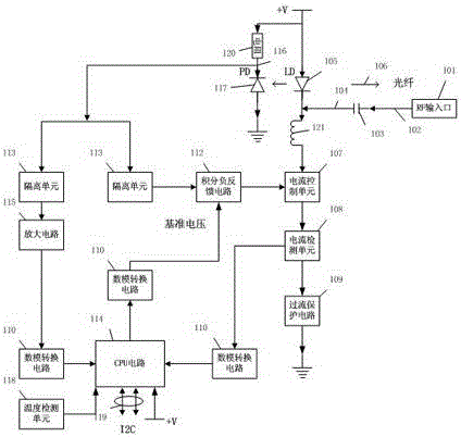
[0052] Embodiment 2 of the present invention sees image 3 , mainly including RF input port 101, DC blocking capacitor 103, microstrip matching line 104, laser LD105, laser backlight detector PD117, broadband inductor 121, sampling resistor 120, current control unit 107, current detection unit 108, overcurrent protection circuit 109 , digital-to-analog conversion circuit 110 , integral negative feedback circuit 112 , isolation unit 113 , CPU circuit 114 , amplification circuit 115 and temperature detection unit 118 .

[0053]The microwave signal is input from the RF input port 101 and transmitted through the microstrip line 102. It must be blocked by a DC blocking capacitor 103 to isolate the DC voltage of the optical power control system of the optical module from being affected by the outside. After the microwave signal passes through the DC blocking capacitor 103 , modulated on the laser LD105 by the microstrip matching line 104, and the modulated laser signal is output thr...


PUM


Abstract

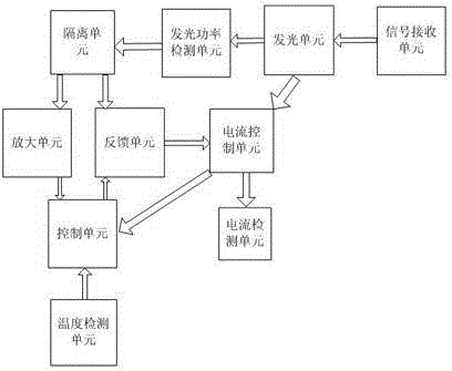
The invention discloses an optical module lighting power control system and a control method therefor. The control system comprises a signal receiving unit, an illuminating unit, an illuminating power detection unit, an isolation unit, an amplification circuit, a current detection unit, a temperature detection unit, a feedback unit, a current control unit and a control unit. The beneficial effects of a technical solution of the optical module lighting power control system and the control method therefor are that intelligent control can be realized according to characteristics of each type of laser device, that output lighting power stabilizes within a 0.5 dB variation range at high and low temperatures of -40 to 85 DEG C can be ensured, working efficiency is greatly improved, the laser device can be prevented from being burnt out, the performance of the laser device can be assessed, service life of the laser device can be determined, early warning can be given in advance, and the laser device can be effectively protected from being burnt out due to excessive currents.

Description

technical field [0001] The invention relates to an optical power device, in particular to an optical power control system of an optical module. Background technique [0002] At present, microwave signals are basically transmitted by microwave cables. However, the differential loss of microwave cables is relatively large, especially for long-distance transmission, and the differential loss is very large, which is too large to meet the needs of the system. Now, some companies have begun to use optical transmission of microwave signals, that is, to directly modulate the microwave signal to the laser, and then transmit it through optical fiber. Because the transmission loss of the laser in the optical fiber is relatively small, the microwave signal can be transmitted over a relatively long distance. In order to modulate the microwave signal to the laser, a microwave optical module is needed, which is actually an electro-optical conversion device. The very key circuit of this ...

Claims


Application Information

Patent Timeline
Patent Type & Authority Applications(China)
IPC IPC(8): H05B37/02
Inventor 付敏何迟光罗国鹏
Owner 珠海天启技术有限公司
Learn More