Composite metal foils, composite metal foils with carriers, metal-clad laminates and printed circuit boards obtained from these metal foils

A technology of metal-clad laminates and printed circuit boards, applied in printed circuits, printed circuit manufacturing, metal layered products, etc., can solve problems such as micro-cracks, lack of flexibility, etc., and achieve the effect of good signal transmission speed

Active Publication Date: 2017-10-13
MITSUI MINING & SMELTING CO LTD
View PDF3 Cites 0 Cited by
  • Summary
  • Abstract
  • Description
  • Claims
  • Application Information

AI Technical Summary

Problems solved by technology

However, the Invar alloy layer of the Invar alloy foil lacks flexibility and is brittle, and micro-cracks will be formed on the Invar alloy layer when slightly bent, so special attention should be paid to the operation

Method used


Image

  • Composite metal foils, composite metal foils with carriers, metal-clad laminates and printed circuit boards obtained from these metal foils
  • Composite metal foils, composite metal foils with carriers, metal-clad laminates and printed circuit boards obtained from these metal foils
  • Composite metal foils, composite metal foils with carriers, metal-clad laminates and printed circuit boards obtained from these metal foils

Examples


Embodiment 1

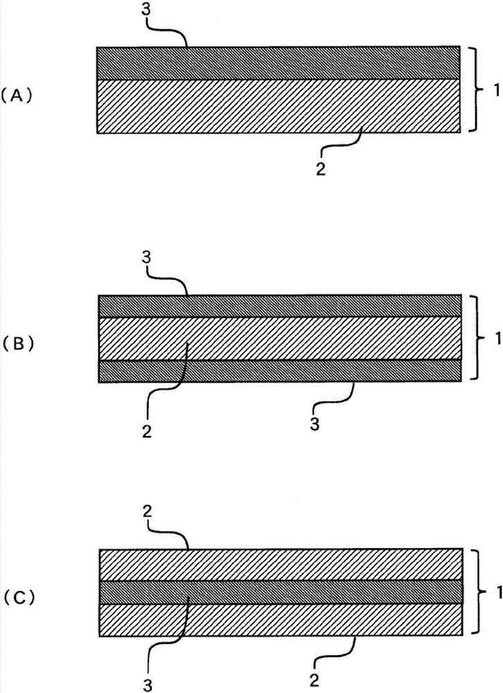
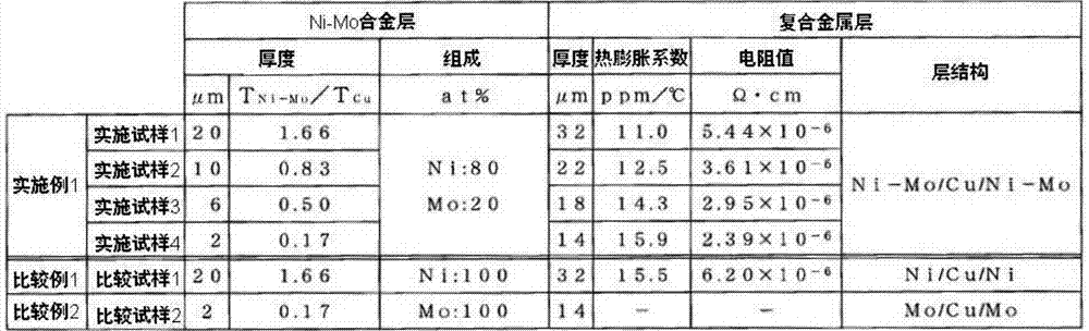
[0073] In embodiment 1, with untreated copper foil (thickness T Cu 12μm electrolytic copper foil), after electroplating the nickel-molybdenum alloy with the thickness shown in Table 1 on both sides (the total thickness of both sides), the obtained figure 1 The layer structure of "nickel-molybdenum alloy layer 3 / copper layer 2 / nickel-molybdenum alloy layer 3" shown in (B), 4 kinds of composite metal foils 1 with equal thickness of the nickel-molybdenum alloy plating layer on both sides (implementation test) Sample 1 to implement sample 4). The nickel-molybdenum alloy plating solution and plating conditions at this time are as follows.

[0074] (nickel-molybdenum alloy plating solution and plating conditions)

[0075] Nickel sulfate hexahydrate: 40g / L

[0076] Sodium molybdate 2 hydrate: 25g / L

[0077] 3 sodium citrate: 80g / L

[0078] Solution pH: 9

[0079] Current density: 16A / dm 2

[0080] Anode electrode: insoluble anode

[0081] Then, the thermal expansion coeffici...

Embodiment 2

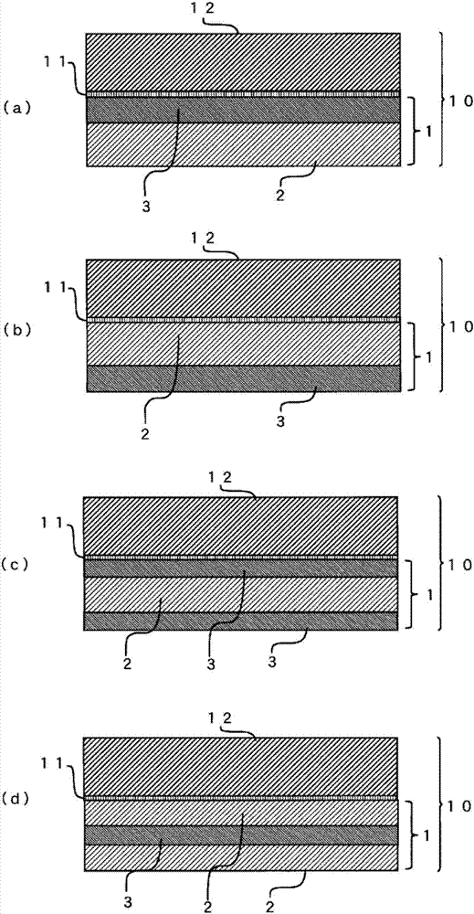
[0105] In embodiment 2, manufactured have figure 2 Composite metal foil with carrier foil with a layer structure of "copper layer 2 / nickel-molybdenum alloy layer 3 / copper layer 2 / peeling layer 11 / carrier 12" shown in (d) (implementation sample 5 to implementation sample 7), and have figure 2 Composite metal foil with carrier foil with a layer structure of "nickel-molybdenum alloy layer 3 / copper layer 2 / nickel-molybdenum alloy layer 3 / peeling layer 11 / carrier 12" shown in (c) (implementation sample 8) . Hereinafter, the manufacturing methods of Example 5 to Example 8 will be described.

[0106] Formation of carrier foils and release layers used in sample 5 to sample 8

[0107] Electrolytic copper foil with a thickness of 18 μm was used as the carrier foil, and on the surface of the carrier foil, the carrier foil was mixed with sulfuric acid 150 g / L, copper concentration 10 g / L, carboxybenzotriazole concentration 800 mg / L, and liquid temperature 30°C. Soak in the dilute su...


PUM

PropertyMeasurementUnit
thicknessaaaaaaaaaa
thicknessaaaaaaaaaa
thicknessaaaaaaaaaa

Abstract

The object of the present invention is to provide a composite metal foil for the manufacture of printed circuit boards, which has three advantages of better low thermal expansion performance than copper, good electrical conductivity, and good solubility in copper etching solution. characteristic. In order to achieve this object, the present invention adopts a composite metal foil, etc., which is composed of one or more copper layers and one or more nickel alloy layers, and is characterized in that the nickel alloy layer is formed of a nickel-molybdenum alloy. When the total thickness of the one or more copper layers is TCu and the total thickness of the one or more nickel-molybdenum alloy layers is TNi-Mo, the relationship of 0.08≦TNi-Mo / TCu≦1.70 is satisfied.

Description

technical field [0001] The present invention relates to composite metal foils, composite metal foils with carriers, metal-clad laminates and printed wiring boards obtained from these metal foils. In particular, it is related with the composite metal foil etc. which consist of one or more copper layers and one or more nickel alloy layers. Background technique [0002] In recent years, along with miniaturization of electrical appliances, electronic devices, and the like, there has been a demand for printed wiring boards having thin, high-density wiring. This kind of printed circuit board is mainly made of insulating layer constituent materials such as metal copper foil, prepreg whose main component is organic material, and resin film. In addition, the thermal expansion coefficients of the copper foil and the material constituting the insulating layer are greatly different, so in the cooling process after a high temperature is applied, the difference in the thermal expansion c...

Claims


Application Information

Patent Timeline
Patent Type & Authority Patents(China)
IPC IPC(8): B32B15/01C25D7/06H01B5/02H05K1/09
CPCB32B15/01H05K3/022H05K3/384C25D1/04C25D3/38C25D3/54C25D3/562C25D7/0614B32B15/018C22C19/03C22C27/04C25D5/14H05K3/025C25D5/60
Inventor 清水良宪松田光由
Owner MITSUI MINING & SMELTING CO LTD
Why Eureka
Try Eureka