Antenna system
一种天线系统、天线的技术,应用在天线、天线耦合、传输系统等方向,能够解决电波接收性能下降等问题,达到抑制接收性能降低的效果
- Summary
- Abstract
- Description
- Claims
- Application Information
AI Technical Summary
Problems solved by technology
Method used
Image
Examples
Embodiment approach 1
[0037] Hereinafter, embodiments for carrying out the present invention will be described with reference to the drawings. In addition, in the drawings for explaining the embodiment, unless the direction is particularly described, the direction on the drawing is indicated, and the direction of the reference in each drawing corresponds to the direction of the symbols and numerals. In addition, directions such as parallel and right angles are directions that allow deviations to an extent that does not impair the effects of the present invention. In addition, as the window glass to which the present invention can be applied, for example, a front window glass attached to the front part of a vehicle, a rear window glass attached to the rear part of a vehicle, a side window glass attached to a side part of a vehicle, a window glass attached to the roof of a vehicle, Skylight glass, etc.
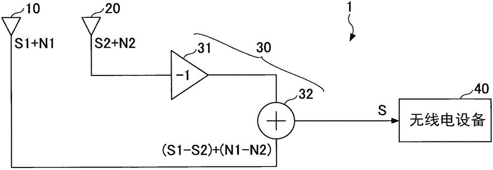
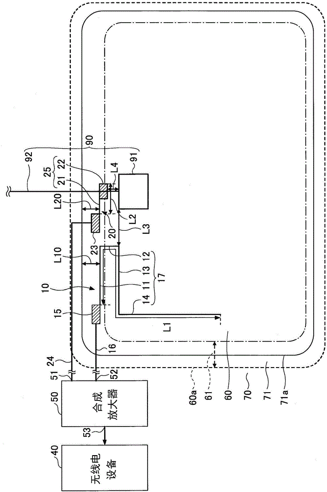
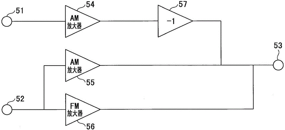
[0038] figure 1 This is a schematic diagram for explaining the configuration of the antenna sys...
Embodiment approach 2
[0086] Figure 7 It is a schematic diagram showing the structure of Embodiment 2. like Figure 7 shown, for a figure 2 The member of the same structure as the shown embodiment 1 is used with figure 2 The marker symbols for the same marker symbols. Descriptions of the same structures as those in Embodiment 1 are omitted.
[0087] In Embodiment 2, the processing of the output cable 93 of the noise source 90 and figure 2 A different example of Embodiment 1. In more detail, figure 2 The output cable 92 extends in the direction away from the window frame, but Figure 7 The output cable 93 of the middle noise source 90 extends along the window frame and is close to the first antenna 10 . In Embodiment 2, both the noise generator 91 and the output cable 93 will be described as noise sources. The noise generator 91 and the output cable 93 are independent noise sources, so the second antenna 20 is preferably installed closer to the noise generator 91 and the output cable 9...
Embodiment 1
[0096] (Conductor length of the first antenna conductor 17 and the second antenna conductor 25)
[0097] The results obtained by actually measuring the gain of the antenna by attaching a window glass for an automobile provided with a glass antenna to an actual vehicle will be described.
[0098] In the AM broadcast band, when receiving radio waves, the conductor length is the main factor compared to the pattern of the antenna conductor. Therefore, in this embodiment, a power supply point is provided at the upper corner of the window glass. The result when the antenna conductor is linearly extended in the lateral direction will be described.
[0099] First, the characteristics of an antenna that is to be received in the AM broadcast band will be described. Figure 9A It is a graph showing the relative relationship between the conductor length of the antenna conductor and the voltage received by the antenna. In other words, Figure 9A It is a graph showing the measured value ...
PUM
 Abstract
Description
Claims
Application Information
 - R&D
- Intellectual Property
- Life Sciences
- Materials
- Tech Scout
- Unparalleled Data Quality
- Higher Quality Content
- 60% Fewer Hallucinations
Browse by: Latest US Patents, China's latest patents, Technical Efficacy Thesaurus, Application Domain, Technology Topic, Popular Technical Reports.
© 2025 PatSnap. All rights reserved.Legal|Privacy policy|Modern Slavery Act Transparency Statement|Sitemap|About US| Contact US: help@patsnap.com


