Supercharge Your Innovation With Domain-Expert AI Agents!

Ceramic press powder grating and ceramic brick forming system and production line using same

A powder grid and press technology, which is applied in the field of architectural ceramics, can solve the problems of blockage of the air outlet of the mold, affecting the fluidity of the powder, and the decrease of the fluidity of the ceramic powder, so as to avoid damage, increase the service life, and increase the density. evenly distributed effect

Active Publication Date: 2016-08-03
FOSHAN DONGPENG CERAMIC +2
View PDF7 Cites 0 Cited by
  • Summary
  • Abstract
  • Description
  • Claims
  • Application Information

AI Technical Summary

Problems solved by technology

[0005] However, the production process of dry granulation will cause the following problems. First, the ceramic powder is an irregular polygon under the microscopic display, which leads to a further decrease in the fluidity of the ceramic powder; secondly, compared with wet granulation , there are more particles with small particle size, and there are more particles with large particle size (as attached Figure 7 As shown), the particle size distribution range is wide, resulting in too little distribution between the particle size of 5-100μm (the most convenient particle size for flow and exhaust), on the one hand, it affects the fluidity of the powder; on the other hand, because the powder The content of fine particles and micro particles in the material is high, and the fine particles will quickly gather around the mold cavity with the overflow of air during compression molding, causing the air outlet of the mold to be blocked and the air cannot overflow. As the air increases, the probability of heavy blanks (also known as spalling) will further increase

Method used


Image

  • Ceramic press powder grating and ceramic brick forming system and production line using same
  • Ceramic press powder grating and ceramic brick forming system and production line using same
  • Ceramic press powder grating and ceramic brick forming system and production line using same

Examples


Embodiment Construction

[0031] The technical solutions of the present invention will be further described below in conjunction with the accompanying drawings and through specific implementation methods.

[0032] In this embodiment

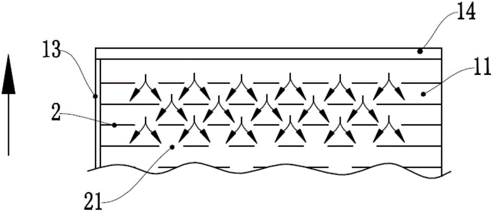
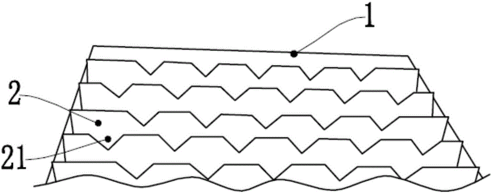
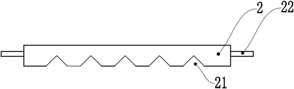
[0033] A ceramic press powder grid (such as Figure 1-3 As shown), it includes a grid frame 1 and several partitions 2, the grid frame 1 is surrounded by longitudinal ribs 13 and transverse ribs 14, and the partitions 2 are horizontally arranged in the grid frame 1, and the The grid frame 1 is divided into several rectangular powder filling areas 11 , and a number of powder openings 21 are provided on one side of the separator 2 , so that two of the powder filling areas 11 communicate with each other. Preferably, the powder openings 21 of the two spacers 2 are staggered from each other.

[0034] The powder grid of the ceramic press in this embodiment, when in use, the distributing machine lays ceramic powder 3 on it, and the ceramic powder 3 is sprinkled on the powder f...


PUM


Abstract

The invention discloses a ceramic press powder grating. The ceramic press powder grating comprises a grating frame and a plurality of spacers. The grating frame is composed of longitudinal ribs and transverse ribs in a surrounding mode. The spacers are transversely arranged in the grating frame and divide the grating frame into a plurality of rectangular powder filling areas. One side of each spacer is provided with a plurality of powder through notches which enable the two corresponding powder filling areas to communicate. The powder grating has the beneficial effects that 1, due to the powder through notches, ceramic powder can flow into the adjacent powder filling areas when the powder grating moves forwards, and local accumulation of the powder is avoided; 2, due to the unique design of the powder through notches, the ceramic powder distributed in a mold cavity is provided with powder convex ribs, the powder can be rapidly and uniformly dispersed during pressing, and the density of pressed green bricks is distributed evenly; and 3, the powder through notches in every two adjacent spacers are mutually staggered, so that the ceramic powder is further distributed evenly.

Description

technical field [0001] The invention belongs to the technical field of building ceramics, in particular to a ceramic press powder grid and a ceramic tile forming system and production line using the same. Background technique [0002] Ceramic brick is a building material with a long history and has been widely used. Before the brick is formed, the ceramic powder needs to be evenly pushed into the mold frame of the forming system through the powder grid, and then pressed by a press. into adobe. At this time, in order to ensure the uniform density of the pressed brick adobe, the process has higher requirements on the fluidity of the ceramic powder. If the fluidity of the ceramic powder is low, the density of the pressed brick adobe will be uneven, and finally Affect the quality of fired ceramic tiles. [0003] Currently generally used powder grids (such as Figure 6 As mentioned above), the powder filling area is a small honeycomb or grid shape. When distributing the ceramic...

Claims


Application Information

Patent Timeline
Patent Type & Authority Applications(China)
IPC IPC(8): B28B13/02B28B3/02B28B15/00
CPCB28B3/02B28B13/029B28B15/00
Inventor 陈智祁国亮徐由强殷少泽周燕罗涛
Owner FOSHAN DONGPENG CERAMIC
Features
  • R&D
  • Intellectual Property
  • Life Sciences
  • Materials
  • Tech Scout
  • Unparalleled Data Quality
  • Higher Quality Content
  • 60% Fewer Hallucinations
Learn More