
Internal combustion engine exhaust temperature control device capable of achieving sectional pressure and temperature adjustment

A technology of pressure temperature and exhaust temperature, which is applied in the direction of exhaust device, electric control of exhaust treatment device, diagnostic device of exhaust treatment device, etc. Exhaust gas temperature requirements are more stringent and other issues

Inactive Publication Date: 2016-08-03
JILIN UNIV
View PDF8 Cites 6 Cited by
  • Summary
  • Abstract
  • Description
  • Claims
  • Application Information

AI Technical Summary

Problems solved by technology

[0002] With the increasingly stringent emission regulations, it is difficult for internal combustion engines to meet emission requirements solely by in-engine purification technology, so exhaust after-treatment technology is particularly important for improving the emission level of internal combustion engines, but the existing after-treatment devices have stricter requirements on exhaust gas temperature , the post-treatment device has a higher conversion efficiency only in a very narrow temperature window, but the exhaust gas temperature of the internal combustion engine for vehicles fluctuates in a large range and is highly transient, which will lead to a poor treatment effect of the after-treatment device, so The purpose of the present invention is to control the temperature of the exhaust gas and control it within the high-efficiency temperature window required by the after-processor, which is of great significance for improving the emission level of the internal combustion engine

Method used


Image

  • Internal combustion engine exhaust temperature control device capable of achieving sectional pressure and temperature adjustment

Examples


Embodiment Construction

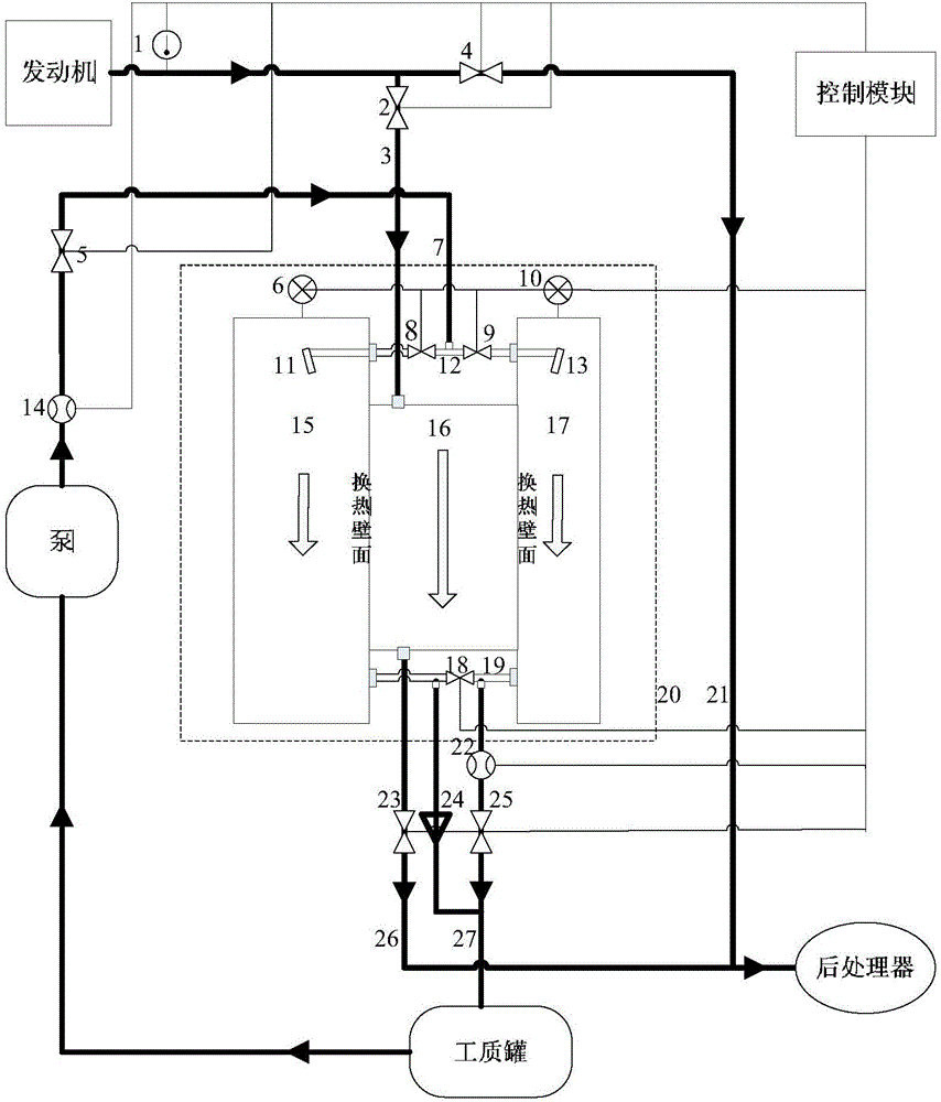
[0018] The following is attached figure 1 The technical scheme of the present invention is described in detail:

[0019] The present invention consists of an exhaust gas temperature sensor 1, an exhaust gas inlet pipe electromagnetic valve 2, an exhaust gas inlet pipe 3, an exhaust gas straight-through pipe electromagnetic valve 4, a working fluid inlet solenoid valve I5, a temperature and pressure sensor I6, a working fluid inlet pipe 7, and a working fluid inlet solenoid valve Ⅱ8, pressure division valve Ⅰ9, temperature and pressure sensor Ⅱ10, nozzle Ⅰ11, communication pipe Ⅰ12, nozzle Ⅱ13, working fluid inflow meter 14, state constant box 15, exhaust gas channel 16, state adjustment box 17, pressure division valve Ⅱ18, communication pipe Ⅱ19, temperature and pressure regulator 20, exhaust gas straight-through pipe 21, working fluid outlet flowmeter 22, exhaust gas outlet solenoid valve 23, safety valve 24, working fluid outlet solenoid valve 25, exhaust gas outlet pipe 26,...


PUM


Abstract

The invention relates to an internal combustion engine exhaust temperature control device capable of achieving sectional pressure and temperature adjustment. The internal combustion engine exhaust temperature control device is mainly composed of a temperature and pressure adjustor, a control unit and various electromagnetic valves. The temperature and pressure adjustor can be used for achieving sectional pressure and temperature adjustment so that a heat storage working medium can be basically kept near a preset target state, meanwhile, high temperature and high pressure are maintained in a state constant box, and the capability of heating low-temperature waste gas is achieved all the time. The heat storage working medium in the temperature and pressure adjustor can absorb and store heat of the high-temperature waste gas, after subsequent low-temperature waste gas passes through, heat can be transferred to the low-temperature waste gas again, and therefore control over the temperature of the waste gas is achieved. A control module controls a path of the waste gas according to a signal of a waste gas temperature sensor, when the temperature of the waste gas is in an efficient temperature window required by postprocessing, the waste gas directly flows into a postprocessor through a waste gas direct-through pipe, and when the temperature of the waste gas is not in the efficient temperature window required by postprocessing, the waste gas flows through the temperature and pressure adjustor to be subjected to temperature adjustment and then flows into the postprocessor.

Description

technical field [0001] The invention belongs to the field of recovery and utilization of residual energy of exhaust gas of internal combustion engines, and also belongs to the technical field of post-treatment of internal combustion engine emissions. Background technique [0002] With the increasingly stringent emission regulations, it is difficult for internal combustion engines to meet the emission requirements solely by in-engine purification technology, so exhaust after-treatment technology is particularly important for improving the emission level of internal combustion engines, but the existing after-treatment devices have stricter requirements on exhaust gas temperature , the post-treatment device has a high conversion efficiency only in a very narrow temperature window. However, the exhaust gas temperature of the internal combustion engine for vehicles fluctuates in a large range and is highly transient, which will lead to a poor treatment effect of the after-treatmen...

Claims


Application Information

Patent Timeline
IPC IPC(8): F01N3/02F01N5/02F01N9/00F01N11/00
CPCF01N3/0205F01N5/02F01N9/00F01N11/002F01N2240/10F01N2560/06F01N2560/08F01N2900/1404F01N2900/1406Y02T10/12Y02T10/40
Inventor 刘金山张成良韩永强王先锋许允田径李润钊种道光
Owner JILIN UNIV
Learn More