
Refrigerating device for downhole instruments

A technology for refrigeration devices and downhole instruments, which is applied in the direction of refrigerators, refrigeration components, refrigeration and liquefaction, etc., and can solve problems such as high cost, limited working hours, and reduced

Active Publication Date: 2016-08-03
XIAN ZHENYU ELECTRON ENG CO LTD
View PDF8 Cites 2 Cited by
  • Summary
  • Abstract
  • Description
  • Claims
  • Application Information

AI Technical Summary

Problems solved by technology

[0003] At present, there are various downhole measurement instruments on the market. In order to ensure that the internal measurement circuit works normally, two methods are usually adopted: one method is to place the measurement circuit and heat absorber inside the metal thermos bottle, and the internal temperature of the thermos bottle will As the temperature rises, the endothermic agent vaporizes, thereby absorbing heat, to reduce various internal temperatures, but this method is limited by the working time. Once the endothermic agent is completely vaporized after a certain period of time, the internal temperature of the thermos bottle will no longer decrease, but with the extension of time, the temperature inside the thermos bottle rises
Another way is to use high-temperature electronic devices to make circuits, which are directly exposed to high-temperature environments. Thermos bottles and heat absorbers are not suitable, but this method is too costly, and some electronic devices cannot withstand high temperatures, which limits the function of measuring instruments. application

Method used


Image

  • Refrigerating device for downhole instruments
  • Refrigerating device for downhole instruments
  • Refrigerating device for downhole instruments

Examples


Embodiment Construction

[0021] In order to better illustrate the structure and working principle of the present invention, a specific embodiment of the present invention will be described in detail below in conjunction with the accompanying drawings.

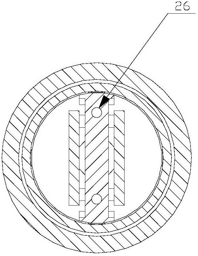
[0022] like figure 1 and figure 2 As shown, the refrigerating device of the present invention includes an upper joint 2, a metal heat-conducting pressure-bearing head 3 and a sealed casing 12, and the upper joint 2, the metal heat-conducting pressure-bearing head 3 and the sealed casing 12 are sequentially sealed and connected to form a The sealing system of the cavity, preferably, a sealing ring is provided at the connection between the sealed shell 12 and the metal heat-conducting pressure receiving head, and a sealing ring is provided at the connection between the metal heat-conducting pressure receiving head 3 and the upper joint 2 .

[0023] In order to illustrate the structure of the present invention more simply and clearly, the following will...


PUM


Abstract

The invention provides a refrigerating system for downhole instruments for oil exploration. According to the refrigerating system, a closed system is composed of an upper connector, a metal heat conduction pressure bearing connector and a sealing shell; and a refrigerating system body composed of an electric motor, a pressure pump, a condenser, an intercepting pipe and an evaporator is placed in the closed system. The evaporator is arranged in a vacuum flask. A circuit board is placed on the evaporator. The internal temperature of the vacuum flask is reduced through the evaporator, so that the internal temperature of the vacuum flask is greatly lower than the temperature of external high-temperature high-pressure mud. A heat absorbent is placed in the vacuum flask. Once the refrigerating system breaks down, the internal heat absorbent absorbs heat in the vacuum flask, and the vacuum flask and heat insulation asbestos isolate the heat conducted by the exterior of the sealing shell. Accordingly, it is guaranteed that the internal temperature of the vacuum flask is maintained within a reasonable temperature range for a certain time period, and the internal temperature of the vacuum flask can be monitored through an internal temperature sensor in real time.

Description

technical field [0001] The invention relates to a refrigerating device for an oil exploration downhole instrument, in particular to a refrigerating device for reducing the working temperature of an internal measuring circuit of an oil exploration downhole instrument. Background technique [0002] In the process of petroleum development, it is necessary to use various measuring instruments to measure various physical parameters of the fluid and rock inside the formation, accurately determine the position of the oil layer, and facilitate the extraction of oil. However, the measuring instruments in deep wells must withstand the high-temperature environment in the well, and it is necessary to ensure that the internal measuring circuits of the instruments work normally. [0003] At present, there are various downhole measurement instruments on the market. In order to ensure that the internal measurement circuit works normally, two methods are usually adopted: one method is to pla...

Claims


Application Information

Patent Timeline
Patent Type & Authority Applications(China)
IPC IPC(8): F25B39/02F25B39/04F25B41/00F25B41/40
CPCF25B39/02F25B39/04F25B41/00
Inventor 王少斌
Owner XIAN ZHENYU ELECTRON ENG CO LTD
Learn More