
Object three-dimensional perspective imaging method and system

An imaging system and imaging method technology, applied in optics, instruments, photography, etc., can solve the problems of slow imaging speed, large volume, and rising manufacturing cost of CT imaging equipment, and achieve the effects of low price, easy operation, and portability

Inactive Publication Date: 2016-08-03
HANGZHOU DIANZI UNIV
View PDF6 Cites 2 Cited by
  • Summary
  • Abstract
  • Description
  • Claims
  • Application Information

AI Technical Summary

Problems solved by technology

The existing 3D CT imaging system obtains a series of data by spirally scanning the object through X-rays, or divides multiple cameras at different angles, and then performs 3D reconstruction of the acquired series of data. The existing 3D CT imaging system Large size, no portable flexibility, and large-scale CT equipment uses large-size digital CCD panels for imaging, because large-size CCDs are expensive, which directly leads to a sharp increase in the manufacturing cost of CT imaging equipment. Therefore, it is necessary to purchase a set of large-scale CT Imaging equipment requires millions of dollars, which is not conducive to the promotion and use of small and medium-sized research institutes, companies, and medical institutions
[0003] The imaging processing algorithm of the traditional imaging algorithm mostly uses the Laplacian pyramid to perform Fourier transformation according to the spatial frequency layer in the realization of the noise reduction function. Some important image content and details are removed, and the traditional imaging processing algorithm image denoising and enhancement are processed separately, so the imaging speed is slow

Method used

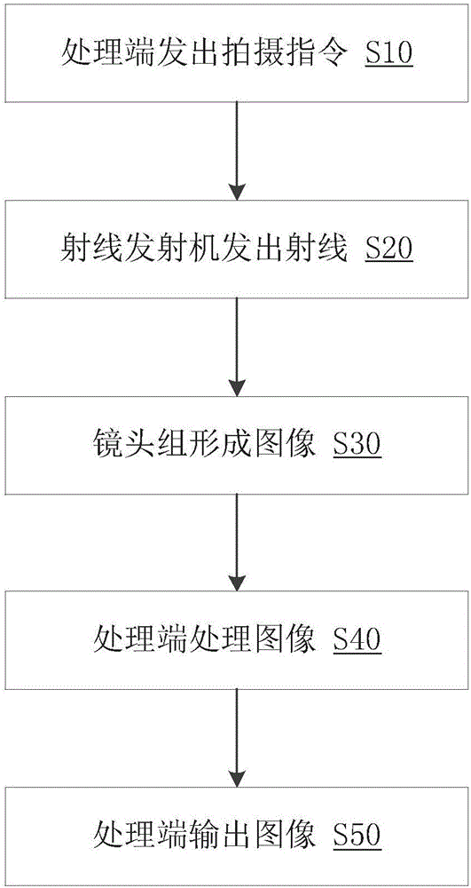
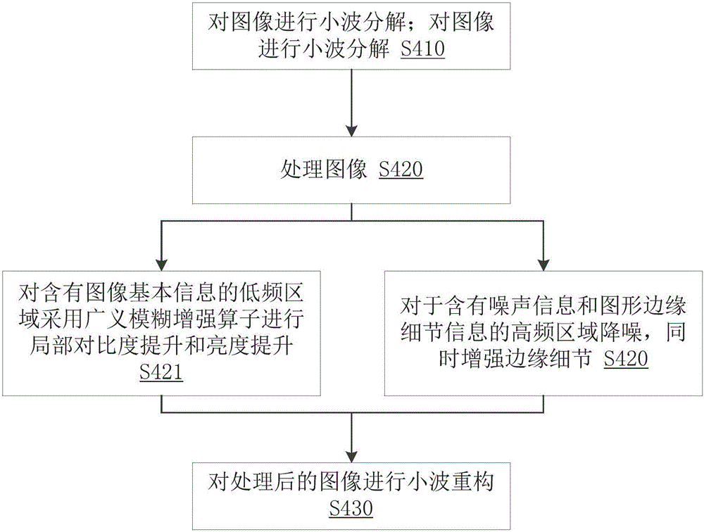

Image

  • Object three-dimensional perspective imaging method and system
  • Object three-dimensional perspective imaging method and system
  • Object three-dimensional perspective imaging method and system

Examples


Embodiment Construction

[0036] In order to make the object, technical solution and advantages of the present invention clearer, the present invention will be further described in detail below in conjunction with the accompanying drawings and embodiments. It should be understood that the specific embodiments described here are only used to explain the present invention, not to limit the present invention.

[0037] On the contrary, the invention covers any alternatives, modifications, equivalent methods and schemes within the spirit and scope of the invention as defined by the claims. Further, in order to make the public have a better understanding of the present invention, some specific details are described in detail in the detailed description of the present invention below. The present invention can be fully understood by those skilled in the art without the description of these detailed parts.

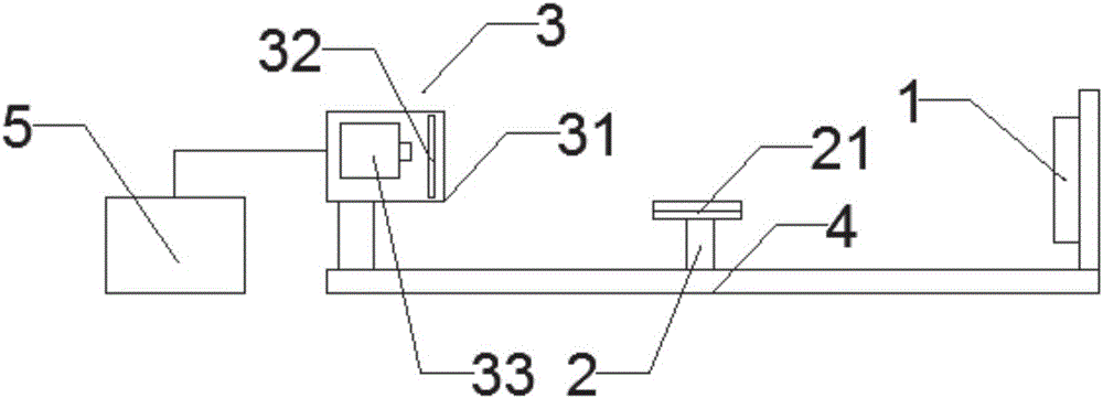
[0038] see figure 1 Shown is the structure diagram of the object three-dimensional perspective imagin...


PUM


Abstract

The invention belongs to the perspective imaging field, and relates to an object three-dimensional perspective imaging system and imaging method. The object three-dimensional perspective imaging system includes a ray transmitter (1), an objective table (2), a lens group (3), a mechanical support (4) and a processing end (5), wherein the ray transmitter (1) and the lens group (3) are respectively fixed at two ends of the mechanical support (4); the objective table (2) is movably arranged on the mechanical support (4); the objective table (2) is provided with a self-rotation motor (21); the processing end (5) is in electric-signal-connection with the ray transmitter (1) and the lens group (3); and the lens group (3) and the processing end (5) are in electric-signal-connection with the objective table (2). The object three-dimensional perspective imaging system has the advantages of being small in volume, being convenient to carry, being simple in operation, having no demand for frequent operation, being clear in imaging and being low in price.

Description

technical field [0001] The invention belongs to the field of perspective imaging, and relates to an object three-dimensional perspective imaging system and an imaging method. Background technique [0002] Radiographic imaging technology is widely used in medical diagnosis, industrial non-destructive testing, scientific research and many other fields. The existing 3D CT imaging system obtains a series of data by spirally scanning the object through X-rays, or divides multiple cameras at different angles, and then performs 3D reconstruction of the acquired series of data. The existing 3D CT imaging system Large size, no portable flexibility, and large-scale CT equipment uses large-size digital CCD panels for imaging, because large-size CCDs are expensive, which directly leads to a sharp increase in the manufacturing cost of CT imaging equipment. Therefore, it is necessary to purchase a set of large-scale CT Imaging equipment requires millions of dollars, which is not conduciv...

Claims


Application Information

Patent Timeline
IPC IPC(8): G03B42/02
CPCG03B42/026
Inventor 郑梁赵存胡炜薇邵李焕郑晓隆
Owner HANGZHOU DIANZI UNIV
Learn More