

Arc welding control method
A control method and arc welding technology, applied in arc welding equipment, welding equipment, manufacturing tools, etc., can solve problems such as timing deviation, and achieve the effect of stabilizing the welding state and maintaining the welding state
- Summary
- Abstract
- Description
- Claims
- Application Information
AI Technical Summary
Problems solved by technology
Method used
Image

Examples
Embodiment approach 1
[0031] The invention of Embodiment 1 sets the cycle and / or amplitude of the feed rate based on the welding speed.
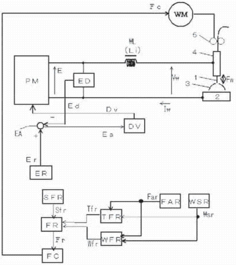
[0032] figure 1 It is a block diagram of a welding power source for implementing the arc welding control method according to Embodiment 1 of the present invention. The following reference figure 1 to illustrate the blocks.
[0033] The power supply main circuit PM receives a commercial power supply (not shown) such as 3-phase 200V as input, performs output control by inverter control or the like in accordance with a drive signal Dv described later, and outputs an output voltage E. Although not shown in the figure, this power supply main circuit PM includes: a primary rectifier for rectifying a commercial power supply; a smoothing capacitor for smoothing the rectified direct current; and the aforementioned drive signal Dv for converting the smoothed direct current into a high-frequency alternating current. The drive inverter circuit; the high-frequency transf...
Embodiment approach 2
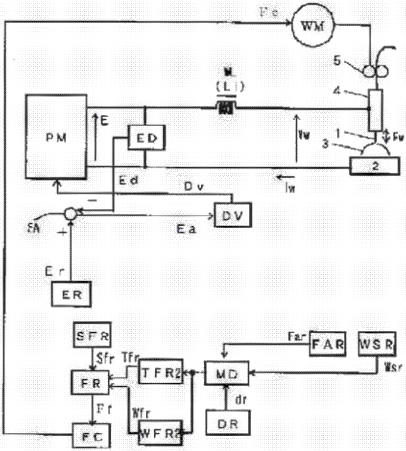
[0049] In the invention of Embodiment 2, the cycle and / or amplitude of the feed rate are set based on the welding wire deposition amount per unit welding length.
[0050] Assuming that the radius of the welding wire is d (mm), the average feed speed setting signal Far (mm / min) and the welding speed setting signal Wsr (mm / min) are input, and the welding length per unit can be calculated by the following formula The amount of welding wire deposition Md (mm 3 / mm).
[0051] Md=π·d 2 ·Far / Wsr…(1) type
[0052] figure 2 It is a block diagram of a welding power source for implementing the arc welding control method according to Embodiment 2 of the present invention. figure 2 with the above figure 1 Correspondingly, attach the same label to the same block, and do not repeat their descriptions. figure 2 exist figure 1 On the basis of the welding wire radius setting circuit DR and the welding wire deposition amount calculation circuit MD per unit welding length are added, t...
Embodiment approach 3
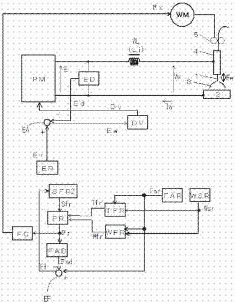
[0060] The invention of Embodiment 3 controls the feed speed based on Embodiment 1 or 2 so that even if the amplitude (amplitude setting signal Wfr) changes, the average value of the feed speed becomes constant.
[0061] image 3 It is a block diagram of a welding power source for implementing the arc welding control method according to Embodiment 3 of the present invention. image 3 with the above figure 1 Correspondingly, attach the same label to the same block, and do not repeat their descriptions. image 3 exist figure 1 On the basis of adding the average feed speed calculation circuit FAD and the feed error amplifier circuit EF, the figure 1 The forward feed side shift amount setting circuit SFR is replaced by the second forward feed side shift amount setting circuit SFR2. The following reference image 3 Describe these blocks.
[0062] The average feed speed calculation circuit FAD receives the feed speed setting signal Fr as input, calculates the average feed s...
PUM
 Abstract
Description
Claims
Application Information