Replaceable heel high-heeled shoes
A replaceable, high-heeled shoe technology, applied in the direction of heels, footwear, heel pads, etc., can solve the problems of complicated processing technology, lack of elasticity, complicated operation, etc., to achieve high material utilization and strength performance, dispersed materials Loss and strength loss, the effect of simple replacement steps
- Summary
- Abstract
- Description
- Claims
- Application Information
AI Technical Summary
Problems solved by technology
Method used
Image
Examples
Embodiment 1
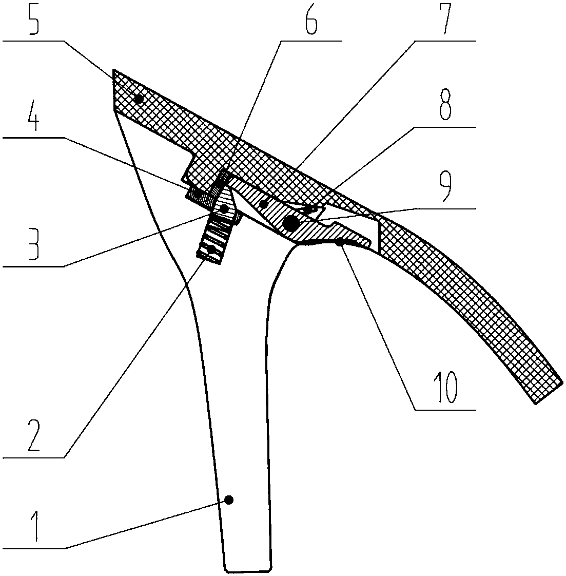
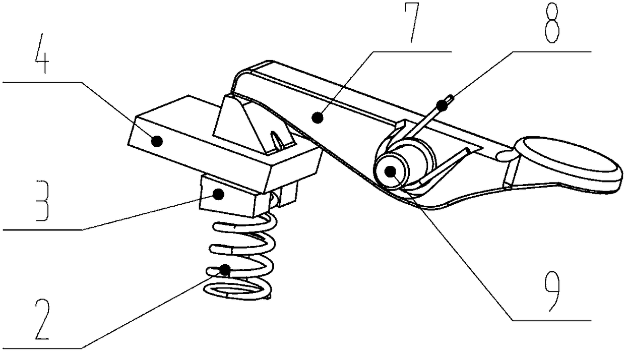
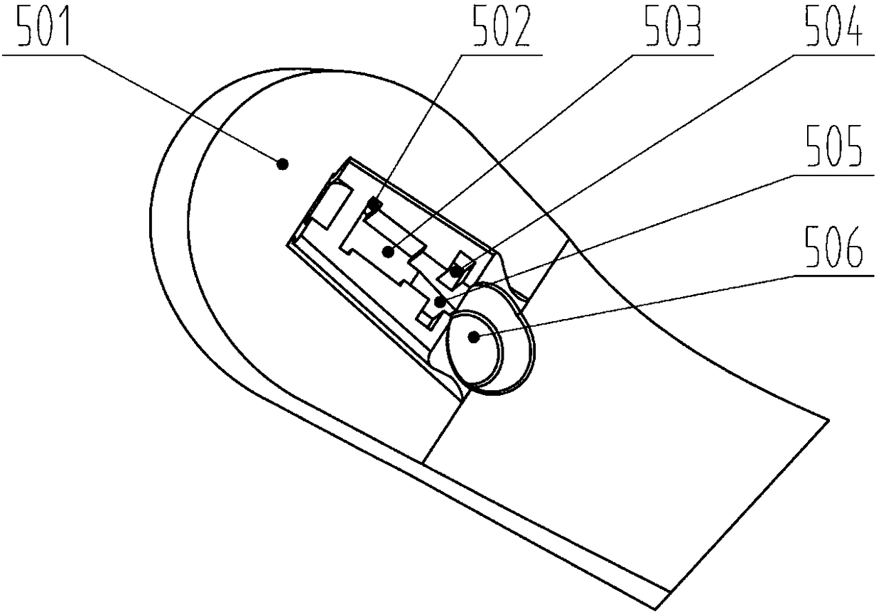
[0039] Example 1: figure 1 It is a schematic diagram of the overall structure of Embodiment 1 of the present invention. A replaceable heel high-heeled shoe includes a sole 5 and a heel 1. A heel-removing and docking device is provided between the sole 5 and the heel 1 of the high-heeled shoe. The heel-removing and docking device includes The clamping structure includes an elastic top rod fixed on the heel 1 and clamped to the sole 5, and a pressing rod structure fixed on the sole 5 to drive the elastic top rod away from the sole 5, and the clamping structure includes a top clamp on the heel 1 The groove and the clamping block connected with the clamping groove are arranged on the sole 5, and the clamping block is formed by the first groove 501 on the sole 5. The bottom surface of the first groove 501 is parallel to the upper plane of the heel 1, elastic The ejector rod is located in the card slot of the heel 1, figure 2 It is a schematic diagram of the structure of the pressin...
Embodiment 2
[0042] Embodiment 2: In this embodiment, the button 10 and the pressing rod 7 are integrally formed, the soft rubber pad on the button 10 and the sole 5 are glued into one body, and the soft rubber pad and the pressing rod 7 are fixed together, which is convenient for assembly. The fixed shaft 9 is two half shafts protruding from the side of the pressing rod 7 and integrally formed with the pressing rod 7. It is fixed to the fourth groove 504 by interference fit, and the second spring 8 is not provided because the sole 5 and the shoe In the process of combining with 1, the movable ejector rod 3 of the elastic ejector rod will press against the end surface of the pressing rod 7 to reset it. The shape of the button 10 is a disc or polygon, and the shape of the sixth groove 506 is a circle or polygon. The bottom surface of the groove of the fixed wear-resistant metal sheet 6 forms an included angle of 15 degrees with the upper plane of the heel 1. A reinforcing rod is provided in t...
Embodiment 3
[0043] Example 3: Figure 5 It is a schematic diagram of the sole structure of embodiment 3 of the present invention. In this embodiment, the fixed shaft 9 is a shaft that passes through the through hole of the pressure rod 7 and forms a 90-degree angle with the side of the pressure rod 7, and is fixed on the sole 5 by interference fit. In the slot 12 or through hole, the material of the heel 1 and the sole 5 is 304 stainless steel. There is no fixed piece 4, wear-resistant metal piece 6 and soft rubber pad. The soft rubber pad does not affect the function. The movable top rod 3 It is directly buckled on the flange of the second groove 502. The first spring 2 is an air spring. The reinforcing rod and the upper plane of the heel 1 form an angle of 65 degrees. The middle of the heel 1 is provided with a reinforcing rod. The upper plane of the heel 1 forms an included angle of 70 degrees. The contact surface of the movable top bar 3 and the flange of the second groove 502 forms an ...
PUM
 Abstract
Description
Claims
Application Information
 - R&D
- Intellectual Property
- Life Sciences
- Materials
- Tech Scout
- Unparalleled Data Quality
- Higher Quality Content
- 60% Fewer Hallucinations
Browse by: Latest US Patents, China's latest patents, Technical Efficacy Thesaurus, Application Domain, Technology Topic, Popular Technical Reports.
© 2025 PatSnap. All rights reserved.Legal|Privacy policy|Modern Slavery Act Transparency Statement|Sitemap|About US| Contact US: help@patsnap.com


